An Apple Pie From Scratch, Part V Supplement: Tectonics: Using Gplates

This post is a supplement to Part Va;
that post described how to simulate plate tectonics conceptually, in terms of
what overall patterns of drift, collision, rifting, and so on to expect. This
post will be more technical, describing how to use Gplates to turn that concept into a tangible reality. Gplates is primarily
designed for use by geologists, and by the standards of similar programs it is
amazingly intuitive; but users from the worldbuilding community usually find it
awkward to use at first. I still hold that playing around with the program is
the best way to overcome that, but hopefully this tutorial will give you a bit
more direction.
If you'd rather go through this in video form, friend of the blog Artifexian has been working on replicating this tutorial in his "Artifexia" video series (starting with Part 9).
If you'd rather go through this in video form, friend of the blog Artifexian has been working on replicating this tutorial in his "Artifexia" video series (starting with Part 9).
- Basics
- Making and Moving Plates
- Making a Rift
- Splitting a Feature
- Making a Rotation File
- Moving the Plates
- Checking and Finalizing Plate Motion
- Making Flowlines
- Adding Ocean Crust
- Adding Subduction Zones and Island Arcs
- Complex Plate Interactions
- Importing Rasters
- Splitting Comoving Plates
- Making a New Plate
- Subducting Ocean Crust
- Colliding Continents
- Splitting Plates After a Collision
- Marking Resulting Features
- Finishing and Exporting
Basics
Basic use of the program, and the procedure to draw, create,
and save “features”.
Startup
Installation of Gplates is straightforward: Follow the
instructions below the download link
for your operating system. I’m using a Windows PC to make this tutorial, so if
you have something else you may find that the appearance and shortcuts are
slightly different.
Once you have it installed and open, you’ll see a lot of
available tools and options, but many of these are designed for reconstructing
Earth’s tectonic history based on geologic evidence, and aren’t useful for
building a new world’s history. Don’t worry about what something like the
“Hellinger” tool does, as we won’t be using it.
The window should have a list of toolsets on the right side,
which can also be selected with hotkeys from “1” to “7”; some
individual tools have their own letter hotkeys (though similar the same hotkey
may select different but similar tools, depending on which toolset you have
open). We’ll mostly just be using the top 3 and the 5th sets.

The “View” toolset (hotkey “1”) includes the
movement tools, but even with other tools open you can hold down the “ctrl”
key and drag the globe or map with your mouse, and use your mouse scroll to
zoom in and out.
Most of what we’ll be doing is handling features:
sets of points, lines, or polygons on the globe’s surface.
The “Feature Inspection” toolset (“2”) includes tools to select
and edit features, the “Digitisation” set (“3”) includes tools to
create new features, and the “Pole Manipulation” set (“5”)
includes tools to move features.
One tool you may use a lot is the Measure tool (“S”),
which allows you to click 2 points on the globe to see the distance between
them, even if the planet’s size differs from Earth’s (by altering the “Earth
radius” value in the upper right in kilometers).

Timescale
The bar along the top handles the timescale, on a scale of
millions of years before the present (Ma); Gplates isn’t built to
handle timescales extending into the future. By default the scale only extends
to 200 Ma, but you can select the number in the upper left and enter a higher
value (you can also change the default timescale permanently in the
preferences); I used 1000 Ma for modeling Teacup Ae, but it’s probably more
prudent to use at least 2000 Ma to give yourself plenty of breathing
space, especially if you want to use longer supercontinent cycles or have an
endpoint later in the second cycle than Earth or Ae.

Once you’ve set that, you can use the scroll bar to look
through your world’s history and use the play button to see features moving
once you’ve added some. But when adding or moving features it’s best to do it
at particular time steps, so you should type in a precise time.
To get started making features, set the time all the way
back at the start (2000 Ma, if you’re using that).
Making your First Supercontinent
We’ll start out simple: A cluster of cratons and a
landmass enclosing them.
To make a craton—or any other polygonal feature—select the “Digitise
New Polygon Geometry” (“G”) tool in the “Digitisation”
toolset (“3”).

Then draw an object by clicking on the globe to draw
vertices; the tool will draw in lines between them, including one from the last
vertex you place to the first to close the loop. “Ctrl-Z” will delete
the last placed vertex like you’d expect, and you can also use the “Move
Vertex” (“V”), “Insert Vertex” (“I”), and “Delete
Vertex” (“X”) tools to alter the feature as you create it, or analogous
tools in the “Feature Inspection” toolset to alter the feature after
you’ve created it.

Cratons in real life have ill-defined and malleable borders,
so don’t worry about shape too much beyond “roundish”, “oblong”, “curved”, and
so on. Size varies quite a bit, but we’re only worried with the largest ones
here, so somewhere around 1-4000 km is about right.

Once you’ve drawn it, select “Create Feature” in the
lower right.

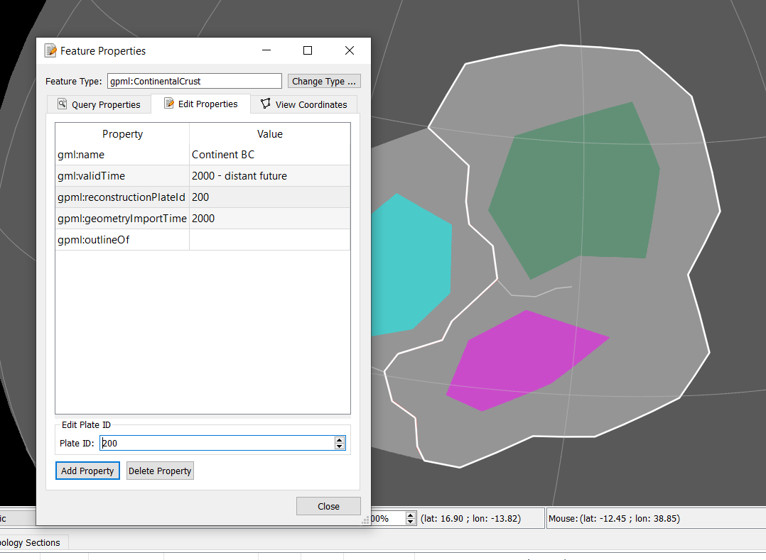
This will bring up a new window asking you to select a feature
type from a long list. Most of these are just different names for features
that behave identically in the program, but a few do behave differently so just
select “Craton” and “Next”.

Next we have to define some properties:
- Leave “Geometry Property” on “Outline”. We shouldn’t ever need to alter this property from the default for any of the features in this tutorial.
- “Plate ID” is used to identify objects that are on the same tectonic plate, and so move together. We’ll discuss how to make that work later, but for now let’s just give each of our cratons its own plate ID, even those we want to initially move together. The IDs are numbers, and we shouldn’t give any features an ID of “0”, as that’s reserved for the immobile “rotation” axis. Let’s give this first craton an ID of “100”.
- “Begin (time of appearance)” and “End (time of disappearance)” define the period of the planet’s history over which this feature exists, and we’ll play around with it later as features are created, destroyed, or change. But the cratons should persist throughout this whole period we’re simulating so select the options for “Distant Past” and “Distant Future”, indicating the feature should exist at all times even if we changed the timescale.
- “Name” is, of course, just a name to keep track of the object. Multiple objects can have the same name, but in this case let’s name this feature “Craton A”.
- Important note: I've heard from some users that using non-Latin characters (letters not used in English, like Cyrillic characters) can cause issues, such as files not saving properly. This should only apply to the names of feature collections and project files, but it's probably best to just stick to Latin characters everywhere. It seems to apply to the folders the files are held in as well, so make sure your whole filepath contains only Latin characters if possible.

All that done, press “Next” to continue. We don’t
need to do anything with the next window, so press “Next” again.
Finally, it’ll ask us to place the feature in a feature
collection. The appearance of features in a collection are altered
together, so we’ll use these to arrange features we want displayed in a similar
way; cratons, continents, subduction zones, etc.
Because this is our first feature, our only option is to “Create
a new feature collection”. Press “Create and Save”.

This will open the “Manage Feature Collection”
window, which for now contains only your new feature collection. Press “Save
As” to name your feature collection (let’s call this one “cratons”; again, avoid non-Latin characters)
and save it. Each feature collection will be saved as a separate file, so
you’ll want a dedicated folder to keep them all together.

After that you can close your window and you should see your
craton has a nice blue color. These colors are assigned by plate ID, so as you
add each craton with a new ID it should have a different color (though there
are a limited number, so eventually you may get duplicates).

Keep adding cratons in the same way, clustered together but
with some space between them. Give each a new plate ID, and rather than
creating a new feature collection for each craton, select the existing “craton”
feature collection (the window will list it with the full file path) and press
“Create” rather than “Create and Save”. For a world with
Earthlike land area and tectonic activity around 8-12 cratons is probably
ideal, but to keep things simple in this tutorial I’ll just make 3; In addition
to craton A, cratons B and C, with plate IDs 200
and 300.

When you have all your cratons down, you can draw another
polygon encompassing all of them, which will be your initial supercontinent.
It’s reasonable—encouraged, even—to have large stretches of land outside the
cratons.

One issue you might run into is that if your
supercontinent’s longest axis extends more than halfway around the planet, GPlates
won’t be able to tell which part of the world is inside the polygon and which
part is outside, which will create issues with filtering rasters and so on.
Fortunately, this should be fixed when we break this supercontinent apart later
on.
Create this feature like you did with the cratons, but with
a few different steps:
- For feature type, select “ContinentalCrust” rather than “Craton” (I’m not sure this actually amounts to anything, but it’s good to keep things organized).
- This continent won’t be moving independent of the cratons, so rather than a new plate ID we’ll just give it the same ID as one of the existing cratons—say, that of the first craton, 100.
- We’ll name it, say, “Continent ABC”, after the cratons it contains.
- We’ll make a new feature collection for it, “continents”.
And lo, we have our first supercontinent. Before you do
anything else, select the “Choose Feature” tool (“F”) in the “Feature
Inspection” set, select your continent, and then switch to the Measure
tool (“S”). The info pane on the right will include a measure of your
continent’s area. Because your supercontinent is the only landmass on the
planet, this will be the total land area of the planet.

Compare this value to the total land area of the planet,
which is [ 4 * π * (radius)2], or 510 million km2 for Earth’s
radius. Recall that a planet with 1/4 of its surface area covered in
continental crust roughly matches Earth’s condition 1 billion years ago, and
modern plate tectonics may be impossible once over 1/2 the planet’s area is
covered in continental crust. My small supercontinent occupies less than 5% of
the area of this planet, which is still reasonable if you don’t want much land
area.
To help us keep track of things, you can select “Window”
-> “Show Layers” from the toolbar on top to open the layers window.
This lets you make feature collections visible or hidden and alter their
stacking order (higher feature collections appear above lower ones) and also
has a dropdown menu for altering the appearance of features in each collection:
You can “Fill polygons” to fill the polygon features with their outline
color, alter the “Fill opacity”, and the “Set Draw style…” menu
can alter the color set, or set all features in the collection to the same
color, or color them by age, etc.

For now I’ve set the continents to be filled with white at
an opacity of 0.2, and the cratons to be filled based on their plate ID with an
opacity of 0.5, which will help us keep track of land areas once we start
adding ocean crust and other features.
Saving the Project
One last thing we should do now that we’ve got some features
down is save the project, which we have to do in two steps. Open “File”
-> “Manage Feature Collections”, and in the window press “Save All
Changes”. The list of features should change from red to white. Then open “File”
-> “Save Project As…” and save it in the same folder as your feature
collections. This is the file you’ll open to get the project back, but all the
feature collection files are necessary for the project, so keep them packaged
together.
Once more, remember that GPlates may have issues with non-Latin characters in its filepaths.
Once more, remember that GPlates may have issues with non-Latin characters in its filepaths.
Making and Moving Plates
This is the core process of this simulation, and the main
reason for using GPlates. It’s a bit awkward at first, but with repetition
you’ll get used to it.
Making a Rift
Obviously, this supercontinent is not long for this world;
we’ll start the simulation by rifting it apart. Supercontinent rifting can be a
multi-step, complicated process, but in this case we’ll just do a clean split
down the middle, sending Craton A west and the other cratons east.
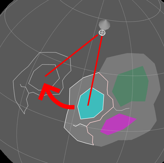
 |
| Red line and arrows added by me outside GPlates |
Whenever I rift a continent apart, I like to draw the rift
as a distinct, immobile feature, to help me keep track of how the continents
move compared to the initial rifting spot. You can do this by selecting the “Digitise
New Polyline Geometry” tool (“L”)—not the polygon tool—and placing a
line across the center of the continent. In this case you’ll see that
subsequent vertices are connected by the program, but not the last to first.
Remember that these rifts are formed by the joining of triple junctions, giving
them an overall zig-zag shape, and that the rift shouldn’t pass through any of
the cratons.

Select “Create Feature” as with any other feature, and proceed through the windows:
- Set the feature type as “ContinentalRift”.
- Set the plate ID as, say, “1”, which I reserve for immobile objects (you could put them in 0 with the rotation axis, but I prefer to just leave that alone).
- Unlike the previous features, we’ll have this one begin when rifting begins (2000 Ma in this case) and then continue into the distant future (this doesn’t matter much at the start of the timeline, but it’s good practice for when we make more rifts later).
- For naming, I tend to just name small objects like rifts, subduction zones, and island arcs after the year they form, e.g. “rift 2000”, which helps keep track of their age if we have to replace the feature later.

We can also make a new feature collection for rifts, and
give them a color like red to stand out.

While we’re on that, we can also create failed rifts,
which don’t split the landmass but can cause new rifts and river valleys later
on, at each of the triple junctions. We’ll use the polyline tool and make the
feature type “ContinentalRift” like the main rift. But we want these
features to move with the continents, so we’ll assign each the same plate ID as
the nearest craton on the same side of the nearest rift, tying the rift’s
motion to that craton.
If you can’t remember the plate ID, you can use the “Choose
Feature” (“F”) tool to select a feature and see some info about it
near the bottom of the window (it’ll display the info for all objects near
where you’ve clicked, so don’t worry about selecting the exact feature). Don’t
be alarmed that the rift you’ve drawn disappears when you select this tool;
it’ll appear again when you return to the digitise tools.

Create the feature with that plate ID, and beginning at the
same time (2000 Ma) as the main rift. Let’s also create a new feature
collection for failed rifts, and give them a more muted silver color.

Splitting a Feature
So that tells us where the rift is, but if we’re going to
split this supercontinent into 2 continents, we’ll need more than the one
continent feature we have. There’s no tool for cutting polygons apart (there is
one for polylines), but a couple tools we can use to make new features.
First off, select your feature (If you ever have trouble
selecting from multiple features, use the list at the bottom) and select the “Clone
Feature” option on the right.

Place it in the “continents” feature collection when
prompted, and you’ll get a new feature identical to the original continent,
including plate ID and beginning and ending times. We gave the supercontinent
the same plate ID as craton A, so we’ll convert this clone into the section
containing that craton. Select the “Move Vertex” tool (“V”) on
the left, making sure you’re in the “Feature Inspection” toolset (“2”).
You should see the vertices of the continent as white
points, which you can now click and drag to move. Leave those on one side of
the rift unmoved, and move those on the other side to match the rift. Don’t spend
too much time trying to line them up exactly; it’s not as if actual continents
perfectly preserve their shape after rifting anyway.
If, like me, you run short of vertices, you can use the “Insert
Vertex” (“I”) tool to add more; if you end up with spare, you can
use the “Delete Vertex” (“X”) tool to remove them. Ultimately,
you should end up with a feature encompassing the entire former supercontinent
on one side of the rift.

Return to the “Choose Feature” tool (“F”) and
select “Edit Feature” (“ctrl-E”) on the right.

This will bring up a window allowing us to alter some of the
feature’s properties. In particular, we want to change the “gml:validTime”
property; un-select “Distant Past” and set the feature to begin at 2000
Ma, when the supercontinent rifts. To keep things straight, we should also
change the name to “Continent A” to match the cratons it contains.

Repeat the same process again to create a “Continent BC”,
but this time when editing the features also change the plate ID to match that
of one of the cratons it contains—say, 200 for Craton B.
Finally, select the original Continent ABC feature,
and set it to end at 2000 Ma. This doesn’t matter much at the beginning
of the simulation, but when you repeat the process for rifts later in the
simulation, the result will be that you have one feature up to the time of
rifting that instantly splits into two objects at the time of rifting that can
then drift independently.

In principle we could also do this in reverse to merge
features, But I prefer to preserve boundaries in case there’s a later rifting
event that breaks along that same boundary, and also because it may help in
drawing topography later on.
Making a Rotation File
To move plates over time and record these movements, we
first have to create a rotation file.
Open up a basic text editor (I like to use Notepad++) and
input these lines (you don’t actually need more than one space between columns,
but it helps keep things organized):
100 2000.0 90.0 0.0 0.0 000 !
Each line describes the position of a plate at a given point
of time, and each column describes some aspect of the plate or motion, like so:
Plate ID
|
Time
|
Latitude
|
Longitude
|
Angle
|
Conjugate Plate
|
Comment
|
100
|
0.0
|
90.0
|
0.0
|
0.0
|
000
|
!
|
100
|
2000.0
|
90.0
|
0.0
|
0.0
|
000
|
!
|
- Plate ID is, of course, the plate ID that is being described. All features in each plate ID always move together.
- Time designates the time at which the plate has this position. The important thing to remember is that gplates will read this file from the present backwards, as opposed to our simulation process with proceeds from the past forwards; this will come up a few times in later steps.
- Latitude, Longitude, and Angle describe the position of the plate in terms of an Euler rotation. You don’t have to worry too much about what this means for now, but in short latitude and longitude describe the position of a rotation axis on the globe, and the angle describes the rotation of the plate around that axis. The rotation at time 0.0 should always have latitude 90.0, longitude 0.0, angle 0.0, indicating no rotation (changing it will cause issues with some features later). Presuming we want objects at the start of the simulation to begin where we draw them, the plates should have the same rotation at the start (time 2000.0 in this case).
- Conjugate Plate allows us to define the position of one plate relative to another. Entering 000 defines the position relative to the unmoving “rotation” axis, and so basically allows us to move that plate independently. Setting it to another plate ID will cause this plate to follow all that plate’s movements (it can still have some movement of its own relative to that other plate). So, for example, if we want Craton C to follow Craton B at the start of the simulation, we can set the conjugate of C’s plate, 300, to be B’s plate, 200. Now when we move Craton B, C will follow it.
- Comment allows you to place any notes after it; name of the plate, events happening at a certain point, etc. Even if you don’t use it, you still need to place the exclamation mark.
So here’s how that all appears for my supercontinent, with
Continent A splitting from Continent BC:

Once you’ve got all that, save the file alongside your
feature collections as “rotation.rot” (set “save as type” to “all
types” or save it as a .txt file and rename it).

Back in GPlates, select “File” -> “Manage
Feature Collections” (“ctrl-M”), and then press “Open File…”.
Find and select “rotation.rot” and open it. It should load in as a new
feature collection.

Moving the Plates
Finally, the exciting part. The basic process here is to
move time forward in timesteps, move all the plates around, and then move
forward again.
I like to use a timestep of 50 million years—long enough
that we won’t have to do too many to complete the simulation, not so long that
we’re losing important details. If there’s a complex collision I might slow
down to 10 My timesteps in that area, and of course you can decide what to do
for yourself.
Whatever you decide, set the timeline forward by one
timestep—to 1950 Ma in this case—and select the “Pole Manipulation”
toolset (“5”). Then select “Choose Feature” (“F”) and
select a feature with the plate ID of the plate you want to move. Select “Move
Pole” (“O”) and then “Enable pole” on the right. A sort of
round arrow should appear pointing out of the north pole.

Using this tool and the “Modify Reconstruction Pole” tool
(“P”), you can move plates around using Euler rotations, like I
mentioned before. These are a bit awkward to get used to, but using them helps
give you realistic plate motion. In essence you move the pole, and then rotate
the plate around that pole. As you do, the program shows you a “ghost” of where
features in that plate will move to.
 |
| Again, red lines and arrows added outside GPlates |
You can select “Highlight children” on the right so
that the ghost also includes features in other plates tied to move with the
plate you’ve selected, and “Reset Rotation” to undo any movement you’ve
done and start over.

Linear motion and rotation always accompany each other on
the surface of a spherical globe, but you’ll want more of one or the other in
different situations. Placing the rotation pole close to the center of your
plate will give you more rotation, and placing the pole far from the center
will give you more linear motion (there is only one pole shown, but the
rotation axis it represents passes through to the other side of the planet, so
functionally the furthest the pole can get from the plate’s center is 1/4 of
the way around the globe).

You can also move the plate with the pole at one point, move
the pole, and then continue moving the plate.
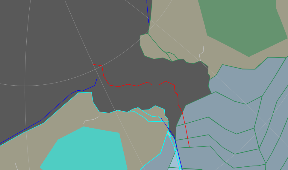
 |
| Blue arrow added outside GPlates as well |
If a plate extends across a large portion of the globe,
movement in one part will manifest as rotation in another, and vice-versa, so
you can’t have one without the other; this tends to limit the lengths of single
divergent or convergent boundaries.
Once you’ve decided on where you want to move the plate,
select “Apply” on the right. Press “Okay” on the window that pops
up, and you should see the features in the plate pop over to where you’ve moved
them.

If you scroll back in the timeline, you can see the plate
smoothly move over to its new position.
Checking and Finalizing Plate Motion
So that's how to move plates, but is the motion realistic? You can
consult the main tutorial
for general patterns, but we can check the speed of plate motion right now.
Select “Utilities” -> “Open Kinematics Tool…”
from the top (“ctrl-shift-K”). In the window that pops up, put in the
plate ID of the plate you want to analyze, set the timescale to the period you
want to look at, and set the “Display type” to “Velocity magnitude”.
You should get a graph of average velocity magnitude over time in the window
for that plate, and you can mouse over it (or check the table above) to see the
velocity over the period of motion in centimeters/year.

I talked about plate speed in the main tutorial, but in short
here are typical values:
Situation
|
Subducting Ocean
|
Recent Subduction Collision
|
Active Margin Continent
|
Passive Margin Continent
|
Plate speed (cm/year)
|
8-20
|
6
|
3
|
<1
|
So my motion for Continent A at ~3.4 cm/year is fast but
reasonable. If you find that your motion is unrealistic, or for whatever reason
you want to change it, then you can move the plate again and apply the new
rotation; so long as you do this at the exact same time as you
originally applied the rotation, it will overwrite that previous rotation, and
the plate will move smoothly to this new position when you look back through
the timeline (you can also reload the “rotation.rot” feature collection, which
will reset all rotations back to the last time you saved them to the file).
To finish up, one issue with simulating plate movement
forwards while GPlates reads the rotation file backwards is that, when you move
the timeline forward again by another timestep, the plate will start shifting
back towards its original position. This isn’t too problematic at the start of
the simulation, but can start getting annoying as you approach the end.
Luckily, it’s not hard to fix: First, open “File”
-> “Manage Feature Collections” (“ctrl-M”) and save the “rotation.rot”
feature collection, which should remove the red highlighting.

Then open the “rotation.rot” file in a text editor
and find the line showing the latest position of the plate other than at 0.0
Ma. Copy this line above it, and change the time column to “1.0”. This
gives that plate the same position at almost the end of the timeline as it has
at the latest point we’ve simulated to (while still not messing with the
position at 0.0, which could cause issues).

Save “rotation.rot” in your text editor, go back to
GPlates, and in the “Manage Feature Collections” window, reload the rotation.rot
feature collection to update it to match the file.

Checking through the timeline, you should see that the plate
no longer moves between the last time at which you’ve moved it and 1.0 Ma, and
then snaps back at 0.0 Ma to its original position. You’ll have to do this
again, at each timestep, for every plate you move in that timestep (you can
leave alone plates that are moving with their conjugate plate but don’t move
relative to the conjugate plate in that timestep). This can be a bit tedious,
so it’s up to you when it’s necessary.
Making Flowlines
Flowlines are useful features to visualize the opening of
new ocean basins and keep track of the mid-ocean ridges. To make one, let’s go
back one timestep to the start of the simulation. Select the rift feature you
made, and select “Copy Geometry to Digitise Tool” on the right.

Then select the “Digitise New Multi-Point Geometry” tool
(“M”) to switch the feature from a polyline to points, and press “Create
Feature” (If for whatever reason you don’t have a rift feature to copy, you
can just select this tool and trace the boundary between diverging plates).
- Select “Flowline” for the feature type.
- Input the plate IDs of the landmasses on either side of the rift (e.g. 100 for Continent A and 200 for Continent BC here). Which is on the left or right doesn’t matter, and the plate IDs don’t have to be those of the objects directly on either side of the rift, though that’s generally a good practice. The plate IDs also don’t have to those of independently moving plates; you can select one being moved by its conjugate plate.
- Have the feature begin at the point of rifting (e.g. 2000 Ma in this case).

In the next window, select the “Add” option. This
will open another window. In the “Insert multiple times” section, input
a “From” time when the rifting starts, a “to” time far later, and
for the “in steps of” option put a some fraction of your timestep; for a
50 My timestep, 10 My works pretty well. Press “Insert” and you
should see a list of times appear in the window above.

Press “OK” and “Next”, and create a new
feature collection for flowlines. When all that’s done, you should be able to
move the timeline forward and, as the landmasses move apart, a series of lines
appears connecting their coasts. The yellow dots in the middle show the position
of the mid-ocean ridge; note how, because the continent motion isn’t
perfectly symmetric, the mid-ocean ridge moves off the position of the original
rift.

One good application of flowlines is that they can help
check for unrealistic plate motions: Adjacent flowlines generally
shouldn’t pass over each other (to a small extent deformation of the crust can
accommodate minor examples of this), and they should never pass over existing
sections of crust, except where subduction is occurring; as a divergent
plate boundary spreads, the flowlines can help you see when it is no longer
possible to have spreading along the whole boundary and you need to add a
subduction zone.
Ideally we could place flowlines first and then see how they
appear when we move plates, but for whatever reason adding rotations to the
plates that flowlines are attached to can cause them to oddly “drift” (it seems
to happen specifically when an existing rotation is overwritten). You may find
that you have to delete and then recreate the flowlines fairly frequently.
 |
| An example of both unrealistic plate motion (flowlines overlapping each other and the continents) and the "drift" I mentioned (the endpoints should be on the coastlines). |
Adding Ocean Crust
Another benefit of the flowlines is they can be used to add
sections of ocean crust. Select the flowlines feature, copy the geometry, and
then select the “Digitise New Polygon Geometry” tool (“G”). This
will give you the start of a polygon with one edge on the mid-ocean ridge, and
then you can trace over the nearby coastline to get a polygon encompassing all
the new ocean area opened on one side of the mid-ocean ridge (GPlates will add
new vertices to one side of the existing line, so make sure you start on the
correct side to get a neat closed loop; and again, don’t spend too much time
trying to exactly line up your new polygon with the coastline).

Press “Create Feature”:
- Select “OceanicCrust” as the feature type.
- Give it the same plateID as the continent it’s attached to.
- Have it begin at the current point, one timestep after the rift opens, as it wasn’t fully formed until now (this means that between timesteps there will just be some open space between the rifting continents, but that’s unavoidable).
- As with small features, I like to name ocean crust pieces after their date of formation, e.g. “ocean 1950”; this gets very useful in keeping track of their ages later on when it may be necessary to replace the features.

Finish creating the feature with a new feature collection
for ocean crust. Follow the same process on the other side of the rift, adding
it to the same feature collection, and we now have our new ocean basin filled
with fresh crust.
In terms of display, it’s useful to have the ocean crust features
retain the colors of their plate IDs to tell them apart when there’s many
crowding the ocean, but perhaps we should give them a very light fill—say, 0.1
opacity.

Going forward one timestep and moving the continents again,
the process of adding new ocean crust will be the same, but this time trace out
the boundaries of the existing ocean crust pieces, rather than the coastlines.
You shouldn’t have overlapping sections of ocean crust except where one is
subducting under another.

Creating the feature is much the same process:
- Give it the same plate ID as the crust section it’s attached to.
- Have it begin at the end of the current timestep, and name it accordingly.
- Put it in the same “ocean crust” feature collection.
And so on, as the ocean continues to grow.
Adding Subduction Zones and Island Arcs
Mid-ocean ridges are only one part of the equation, of
course; as new crust created here, old crust must be subducting elsewhere. Trying
to figure out how subduction would work in the initial ocean without any
initial ocean crust would be a tricky task, but luckily it’s normal for a
supercontinent to start surrounded by subduction zones just before it rifts; we
can just let those subduct away the old oceans.
Return to your first timestep, and look back and forth
through the simulation to try and get a sense of where the leading edges of
your continents are.
 |
| Given motion of the plates (red arrows), I've marked out the leading edges (blue lines) |
Then go back to the start of that timestep, when the continents
start moving, and use the “Digitise New Polyline Geometry” tool (“L”)
to mark out subduction zones just offshore of your continents along their
leading edges. They need not be directly offshore, mind; you can have some
excursions away from the coasts, or pass across the mouths of large bays, and
at the ends of the leading edges of the continent you can have them extend
further outward, so long as they’re still perpendicular to the motion of the
plate.
Press “Create Feature”:
- Select “SubductionZone” for the feature type.
- Give them the plate ID of the nearest craton on the continent they’re formed by.
- Have them begin at the same point you make them—at the beginning of the timestep where the continents start moving, and name them accordingly.

Make a new feature collection for them, and there we are:
Fresh new subduction zones, which should appear as lines colored by their plate
ID.

These subduction zones will, of course, cause volcanism and
the formation of new continental crust on the overlaying plate. Along the
continental coasts this will cause orogenies, but we’ll worry about those
later. A more immediate concern is the creation of island arcs at sea.
My rule of thumb is that island arcs form one timestep—50
My—after the subduction zone first appears (the one exception is at the
very end of the simulation in the last timestep, when even newly formed
subduction zones should get small island arcs). So let’s move forward one
timestep, and then select the “Digitise New Polygon Geometry” tool (“G”).
On the trailing side of any subduction zone in the ocean, start drawing
out an arc of small islands, each no more than a couple hundred miles across.
Rather than tediously drawing a lot of individual features, I
prefer to draw the islands as one object by first drawing one side (the “bumps”
are islands and the straight sections the gaps between them)…

…and then drawing the other side, tracing over the
connecting lines between islands to make bars that should hopefully be too thin
to see on the world map.

Create the feature:
- Feature type “IslandArc” (or ContinentalCrust, it doesn’t really matter)
- The same plate ID as the subduction zone that formed it.
- Beginning at the current time, one timestep after the subduction zone appeared.
- And finally, give it its own feature collection.
And though I’m calling these “island arcs”, they can include
spurs of land attached to nearby continents where the subduction arc passes
from coastline to ocean.

Once we make an island arc, we don’t need to touch it again
unless it’s involved in a collision or rifting event. Actual island arcs
develop more gradually—appearing fairly early and growing over time—but what
we’re drawing here are more abstract representations of island arcs than actual
mappings of islands. Once you’ve finished the simulation, you can edit the
resulting map outside GPlates to add larger islands to old arcs.
One thing to remember about subduction zones is that they
don’t only appear when a continent rifts apart or changes direction; If we say
that these continents are subducting some of the ocean to their south, then as
they move apart that subduction zone will spread along the new ocean’s southern
border. So with each timestep, we have to add new sections of subduction zone
and island arcs on that boundary.

This also has the nice tendency of naturally forming long
arcs, because of how the plates move across the globe.
Complex Plate Interactions
Now that we have a feel for basic plate motion, let’s go through
all the types of rifting, collision, and subduction you should encounter in
simulating tectonic motion.
Importing Rasters
We’re about to move into some more complicated procedures,
where it’s useful to keep track of every individual feature, so we’ll just take
a quick detour to input some rasters to help that process along.
Rasters are just visual overlays on the globe. Any map in an
equirectangular projection—an even grid of latitude and longitude, which is
twice as wide as it is tall—can be imported as a raster; this is a pretty
useful function for gplates even when you’re not using it to simulate plate
motion.
But in this case we’ll just use flat color rasters, like
this 1000 by 500 pixel beige image that will be our “land” raster:

In Gplates, go to “File” -> “Import” ->
“Import Raster…”, and select your raster. The program accepts a pretty
wide range of image file types; I used a .png in this case. Give the raster
band a name if you like, leave the default options on the “Georeferencing”
window, and create a new feature collection.
Once you’ve done all that, you should see the whole world
colored by your raster. Select “Window” -> “Show Layers” (“ctrl-L”)
if you don’t already have the layers window open, and find your raster on the
list. In the “Inputs” menu, find “Reconstructed polygons” and
press “Add new connection”.

From the dropdown menu, select “continents”, or
whatever you’ve named the feature collection containing your continents. This
will now restrict the raster to only appear within the polygonal features in
that feature collection.

Set the rasters “Opacity” down to “0.5” so
that we don’t obscure any underlying features.
Add all your features containing distinct landmasses (just island
arcs for now, but microcontinents, accreted terranes, and continent
fragments later on). Then, in the layers for the continents feature
collection, you can un-select “Fill polygons”, set the “Fill Opacity”
back to ”1.0”, and use the “Set Draw style…” menu to set it back
to color by plate ID. This means that the raster will mark out land areas, and
the features will be neatly outlined with colors matching their plate IDs. We
can do this with ocean plates as well, using another raster (it’s probably best
to place the water layer below the land layer in the list, to avoid confusion when ocean
crust starts subducting).

Hopefully that should make things a bit clearer moving on.
Splitting Comoving Plates
So we know how to tie plates to move together at the start
of the simulation, but what about when we want to rift them apart later on?
Like, say, our Cratons B and C?
To start out with, the procedure is similar to creating our
first rift: We already have a failed rift between B and C, so let’s copy the
geometry of that and extend it outwards (you can use the “Insert Vertex”
tool (“I”) to add new vertices to both ends of the line) But we want it
to extend not only across the continent, but all the way to the mid-ocean
ridges and subduction zones on either side—that is to say, across the whole
tectonic plate.

Make the rift with a beginning at this new rifting point,
have the old failed rift end at the same time, and make new failed rifts
branching out from this new rift (we only need them on land). We can also have
the old rift from the start of the simulation disappear a timestep or two after
it formed to avoid unnecessary clutter and confusion.
Then we can split the continent and other polygonal features
that cross the rift (ocean crust, island arcs) like we did before, by copying
each feature twice and altering the copies to match the shapes of the old
features on either side of the rift, but with different plate IDs.
But rather than having the original features end at the
point of this rifting and the copies begin at the same time, we can just delete
the originals and have the copies exist from the beginning (whenever the
original feature formed), such that there were always two features with
different plate IDs but they were moving together until now. This preserves the
in-program age of the features, which can be useful with “color by age” display
functions later on.
 |
| Split the features at the point of rifting (left) such that they exist as separate features from the start (right). |
At least, we can do this with ocean features; for continents
we’ll probably have to use the “original ends as copy begins” option to account
for deformation in collisions later on.
For features just on one side of the plate, we can just
change the plate ID if necessary, rather than creating a copy. For polyline
features that cross the rift (e.g. that eastern subduction zone) select them
and use the “Split Feature” tool (“T”) to split each into two
features, and change the plate ID of one.

With the features sorted, next we have to edit the rotation
file. Open “File” -> “Manage Feature Collections” (“ctrl-M”)
and save “rotation.rot”. Then open “rotation.rot” in a text
editor.
Find the latest position of the plate you want to split from
its conjugate plate, other than its position at 0 Ma. In this case, we haven’t
moved plate 300 (relative to its conjugate plate) since the start of the
simulation.

Copy that line above, and change the time to that of the
rifting event.

Leave the file open and go back to GPlates. Open “Reconstruction”
-> “View Total Reconstruction Poles” (“ctrl-P”). This will
open up a window showing a list of plates in a cascading tree, showing which
plates are the conjugates of which other plates. Find the plate you want to
split from its conjugate (300 in this case) and look at the last 3 columns,
under “Equivalent rotation rel. anchored plate”. This shows the current
position of this plate relative to whatever plate we’ve set to be the anchored
plate, which by default is 0, the immobile rotation axis.

Create a new line for your plate at the point of rifting, above
the line you just made, and input the same plate ID and time, but copy over the
“lat”, “lon”, and “angle” values from those columns in
GPlates, and set the conjugate plate to “000”. Then copy this
line above again and set the time to “1.0”, or replace a position for
this plate with that time if you already have one.

Save “rotation.rot”, and in GPlates reload it in the
“Manage Feature Collections” window. You should now be able to move the
plate independently of its former conjugate.

You’ll have to add new flowlines, and perhaps remake some
old ones—in this case, the flowlines between Continent A and former Continent
BC have to be remade to connect Continent A to each of the new continents
(splitting the original rift may help).

We’ve also made a triple junction in the mid-ocean ridges
here; When making new ocean crust features, we’ll have to project out their
edges so that they meet roughly in the middle, accounting for the different
speeds of the spreading plates.

We’ll then have to add new flowlines here (3 with 1 point
each, 1 for each plate-plate boundary) to track the position of this extending
section of the mid-ocean ridge, and be sure to trace over them as we add more
ocean crust in the future.
Rifting often comes with changes in direction, so watch out
for new regions of subduction—such as along Continent B’s northern shore here.

Making a New Plate
So that all works to split an existing plate away from its
conjugate, but what if we want to create an entirely new plate partway through
the simulation? What if, for example, we want to split off the eastern part of
Continent C into a microcontinent?

Again, the procedure starts out pretty similar to previous
rifting events: Mark out a rift, tracing any available failed rifts (though you
don’t have to follow the whole rift, you can leave a section behind on one side
or another), and create new failed rifts. Those on the microcontinent side
we’ll give a new plate ID; say, “301”, as a small, probably ephemeral
plate split from plate 300.
For features crossing the rift, create a copy on the side of
the existing plate (Continent C) as you would normally. But for the side with
the new plate (the microcontinent) select the feature and use “Copy Geometry
to Digitise Tool”. Move the vertices to trace out the feature on the new
plate’s side of the rift, as you would with a copy, and then create a new
feature with most of the same properties as the original feature—feature type,
time of appearance—but the plate ID of the new plate (301) and, where
appropriate, a new name (say, “Microcontinent 1” for the main landmass).
We might as well also make a new feature collection for microcontinents, as
opposed to craton-containing continents, and add them to the list of polygons
using the land raster.
We have to do this process—copying geometry and making a new
feature rather than just directly copying the old feature—for every object on
the side of the new plate, even if they don’t cross the rift. Simply changing
the plate ID of a preexisting feature causes it to move elsewhere on the globe,
due to how the position is recorded as a combination of original location and
subsequent rotations.

Now, save “rotation.rot” in the “Manage Feature
Collections” window and open the file in a text editor. Add in two new
lines for the new plate at time 0.0 and the time it rifts from the other
plate (1850.0 here). Give it a position of “90.0”, “0.0”, “0.0”
for lat, lon, and angle as all the other plates start out with, and give it a
conjugate plate of “000” at both times.

Save the file and reload it in GPlates. Now open “Reconstruction”
-> “Specify Anchored Plate ID…” (“ctrl-D”) and enter the plate
ID of the plate your new plate is splitting from (300).

Then open “Reconstruction” -> “View Total Reconstruction
Poles” (“ctrl-P”), find your new plate (301), and look at “Equivalent
rotation rel. anchored plate”. Open “rotation.rot” in the text
editor again, and create a new line for the new plate (301) under the
existing lines, with the same time as the rifting event, the lat, lon, angle
position from the window in gplates, and the old plate (300) as the
conjugate plate. Then copy that line and change the time to the beginning of
the simulation (2000.0).

Save the file and reload it in GPlates. Open “Specify
Anchored Plate ID…” again and set it back to “000”. If you scroll
back through the timeline, you should see that the new plate properly follows
the old plate before the rifting event, but can be moved independently
afterwards.

Subducting Ocean Crust
We’ve covered just about every case of divergent boundaries,
but let’s start thinking more about convergent boundaries. Adding subduction
zones around the exterior of the initial supercontinent is easy enough, but
sooner or later you’ll have to add them between your continents, in the area
covered by new ocean crust. In fact, you should make a point of doing so every
other timestep or so, to add a bit of variety to the process rather than just
marching from one supercontinent to the next.
How new subduction zones form is, as I’ve mentioned in the
main tutorial, not settled science. For our purposes, you can either extend an
existing subduction zone or create new ones at transform rifts. You should
prefer to divide old ocean crust from either newer ocean crust or continents,
but you can cut through similar-age crust where necessary. As a generally rule
of thumb, try to make sure that any ocean crust more than about 3-400 million
years old is heading towards a subduction zone.
In this case, Continent A has been turning north, putting
pressure on the northern side of its attached ocean, so let’s make a new
subduction zone through there.

This, of course, cuts off some of the ocean crust on
Continent A’s plate. For these sections, make a new ocean plate just like we
made that microcontinent plate before (though in this case there’s no need to
bother with a rift feature, as there will be no mid-ocean ridge to keep track
of). Call it, say, Ocean i, with plate ID 101. I’ve also switched
subduction zones to all display as blue to stand out more.
 |
| For whatever reason GPlates picked the same color for plate 101 as for plate 200 (green), but you can tell where it is by the color and direction of the flowlines. |
As we move forward in further timesteps, the ocean plate
will by pulled into the subduction zone, faster than it was moving with the
continent before, and the continent itself will also be somewhat pulled by the
new subduction zone. The opening of a new subduction zone should always be
accompanied by a shift in motion of nearby plates.

Once a section of the subducting plate has completely passed
through the subduction zone, we can set that feature to end to clear up some of
the clutter. But at the same time, new ocean crust will continue forming at the
mid-ocean ridge. With subduction zones on both sides of an ocean basin this can
form a stable “conveyor belt”, with new crust being formed just as soon as old
crust subducts. In this case, with subduction on one side, the mid-ocean ridge
is being pulled towards extinction.

The general rule of subduction zones is that there must
always be ocean crust feeding into them. It can come in directly or at a high
angle, and it can slow to a crawl, but you can’t pull crust out of the
subduction zone. This is easy enough to say now at the start with the tectonics
of the exterior ocean left unmapped, but it can be tricky to pull off once the
entire planet is covered in new plates. In particular, watch out for those
subduction zones on the trailing edges of plates; the ocean crust has to move
towards the subduction zone faster than the subduction zone is receding
away.
In this case, it doesn’t take long for ocean i to be totally
subducted; in one more timestep, the mid-ocean ridge has passed through the
subduction zone. There’s no need to even make a new section of ocean crust for that plate at
this point; we can just set every feature in the plate to end at this point.

This means Continent B’s plate is now being subducted, and
it can be expect to accelerate towards the subduction zone. But the ocean crust
on A’s side of the subduction zone isn’t getting any younger; in cases like
this with an offshore subduction zone, it’s fairly common for another
subduction zone to open up behind it along the coastline, pulling the outlying
subduction in towards shore until it collides with the continent. But in this
case we’ll leave the situation as-is in order to avoid having too many moving
parts in the next section (though over longer timescales, you’ll probably find
that this process helps “clean up” odd subduction zones and islands that are
tricky to deal with otherwise).
Colliding Continents
Continent collisions are, as a rule, messy affairs, and it’s
worth taking our time to move through them. I still make major plate motions in
50 My timesteps, but I then make some changes in finer 10 My steps.
So in this case, we have Continents A and B barreling
towards each other, with an island arc “trapped” between them.

Moving one timestep forward causes the Continents to
collide, with several of their features overlapping—an unphysical situation
we’ll have to resolve. Collisions don’t always end neatly at the end of a
timestep, like this one has; You want the movement rate to be consistent with
the previous timestep, but you don’t want to end up with too much overlap;
cratons in particular shouldn’t overlap each other. This might require you to
move the plate at some point during the timestep, rather than at the end.

First, that island arc: go back through the timestep and
figure out exactly where along the other continent it is colliding.
 |
| Beginning (left) and end (right) of the island arc's collision with Continent A |
Then, at some point during the collision, make a new feature
all along that boundary, representing the accreted terrane formed from
the crust of the island arc. Even though we haven’t been recording the growth
of the island arc after its first appearance, take its age into mind; older
arcs will contain more crust and create larger terranes.

Create the feature:
- Feature type “ContinentalCrust”.
- Plate ID of the continent it’s accreting to (so, 100 here for Continent A)
- Beginning at the point of this collision.
- Name it after that date of collision.
- Create a new feature collection for accreted terranes.
Once that’s done, add that feature collection as an input
for the land raster, and have the island arc end at the same time as that new
terrane appears.

By the way, if you have an island arc colliding with an
island arc, this can create an accreted terrane as well on one of the plates (If
it’s two plates subducting a third between them, place the terrane on the plate
with younger crust in the area, with the subduction zone on that plate
surviving while the other is lost), unconnected to any continent. Usually this
terrane should end up accreting onto a large continent before long, but that
may not happen by the end of your simulation.
With that done, we can move forward to the main part of the
collision at the end of the timestep. When continents collide, much of the crust between them is
compressed and deformed; here, we’ll account for that by redrawing the borders
of the features involved such that there are no overlaps between crust
features.
Select one of the features; I’ll start with Continent A.
Copy it’s geometry, and then move some of the vertices in the new polygon along
the collision boundary such that they create a new ragged boundary roughly
halfway between the boundaries of the overlapping features (you can add some
vertices as well). But some of the compressed crust will be squeezed out to the
sides, so you can expand out the features to either side of the boundary.

Create a new feature with all the same properties as the old
feature you’re copying, but beginning at the point of this collision. Then edit
the old feature such that it ends at the same time.
Repeat this for all the other features deformed by the
collision (in this case, Continent B, the new accreted terrane, and the island
arc on Continent A’s side), making sure that there are no gaps left along the
collision boundary (unless there’s a substantial trapped sea) but no overlaps
between crust features. No major gaps or overlaps, anyway; again, don’t spend
too long trying to get everything to match up perfectly. Note that it’s not
unusual for small features, like that trapped terrane, to moved completely
outside their original position in this process, given that we’re not
simulating the whole process of continuous deformation.
Cratons do deform a little in reality, but not much; for
this simulated process, you should be able to leave them alone, and if that
ends up with them overlapping features outside they’re continent, then you’ve
overlapped the colliding continents too much.
The downside of this process is that it alters the age of
the features. This is an issue only if you want to use some display options
that depend on the age of the features. For example, some of the expanded
continental crust is now overlapping ocean crust features, but I want to
preserve the ages of those. To deal with those, I can split the ocean crust
features into 2 features—one containing all the crust still in the ocean, the
other containing the crust that is now overlapping the land—and edit the one
overlapping the land to end at the point of collision.
Finally, clean up the subduction zones—edit those now
overlapping the landmasses to end at this point (use the “Split Feature”
tool (“T”) to cut those only partially overlapping and make only the
overlapping sections end) and add in extra sections as necessary to fill gaps
along the boundary.

That handles all the features, but the very last step of
colliding the plates is tying the plate IDs together. This works just like
breaking them apart, but with different conjugate plates. In this case, let’s
set plate 100 as the “parent” plate and make plate 200 the “child” plate, tying
it to move with plate 100 as its conjugate plate.
Save the “rotation.rot” file and open it in a text
editor. In GPlates, set the parent plate (100) as the anchored plate, and find
the child plate (200) in the “Total Reconstruction Poles” window. In the
rotation file, make a new line for the child plate (200) above the latest line
in the simulation (which should be the plate’s position at the end of the
collision; 1650.0 Ma in this case) and fill it in with the position data for
that plate under “Equivalent rotation rel. anchored plate” in GPlates,
with the parent plate’s ID (100) in the conjugate plate column. Also copy this
position, with the conjugate plate, to the plate’s position at 1.0 Ma.

Save the “rotation.rot” file, reload it in GPlates,
and set the anchored plate back to 0. You should now find that moving the
parent plate moves the child plate with it. This doesn’t mean you can’t move
the child plate at all; if the collision doesn’t finish in one timestep, you
can continue to move the child plate relative to the parent plate in the next
timestep, as the plates move across the globe together (you will, of course,
have to deform the features again at the end of that timestep to handle this
continued collision).
In this case, there’s still that long subduction zone to the
south where Continent A’s plate is subducting Continent B’s. In an actual
simulation, I’d deal with that either by forming a new subduction zone along
the south coast of combined Continent AB, pulling in the island arc to collide
with the coast and eventually pulling Continents AB and C back together; or I’d
rotate Continent B around until it eventually collided with Continent A’s south
coast. But this tutorial is almost over, so I’ll just ignore them for the sake of simplicity.
Splitting Plates After a Collision
When continents collide, the suture remains as a weak point
in the crust, and new rifts can form there later on (this doesn’t usually
happen immediately, but we’ll do it for the purposes of the tutorial). I won’t
go through the whole process here—it’s essentially the same as the earlier
section on splitting comoving plates. The one note I want to make is that the
rift shouldn't pass exactly over the suture point between pre-existing features;
there is always some exchange of “territory”.

Split the features crossed by this rift much as we
“deformed” them in the last section:
- Copy their geometry.
- Create new features occupying the space of that old feature on either side of the rift (with plate IDs to match the plates on that side).
- Have these new features begin at the point of rifting.
- Edit the old feature to end at the point of rifting.
I’ll leave it up to you whether or not to create a new
feature collection for fragments of continents broken away from the main
continent features.
When you’ve done all that and edited the rotation file to
split the plates again, they should be able to split with everything on the
correct side of the rift.
Not only is this accurate to how old sutures rift in reality, it's also a good way to gradually add more detail to your coastlines.
Marking Resulting Features
That about covers the whole process of plate motion in
GPlates; Continue on to the end of the simulation, following the broad outlines
of tectonic processes as outlined in the main tutorial
and the specific steps as outlined in this one. But when you’re done, you still
have to go back through the timeline and add some features that result
from these plate motions; orogenies, LIPs, and hotspots.
Adding Orogenies
Orogenies are major mountain-building events that
appear along convergent boundaries. As mentioned in the other tutorial, there
are 4 major varieties:
- Andes-type orogenies, which form thin mountain ranges on any coasts with subduction just offshore.
- Laramide-type orogenies, which form broader ranges when subduction is particularly rapid or where a mid-ocean ridge is subducted (the science is unsettled and both are probably contributing factors, but the latter possibility is easier to spot in GPlates).
- Ural-type orogenies, which form thin ranges in simple collisions between landmasses.
- Himalayan-type orogenies, which form broad, high plateaus in more complex or energetic collisions between landmasses.
In GPlates, we can start out by placing Andes-type orogenies
as polygonal features near any coastlines with subduction zones at the start of
the timeline. You can use the measuring tool to get a sense of proper size; 100
km from the coasts and 100 km wide is a good standard.

Create the feature:
- “OrogenicBelt” as the feature type.
- Plate ID matching the landmass it’s on.
- Beginning time matching that of the subduction zone causing it.
- Whatever name you like (“orogeny” and date of formation works fine for me).
- A new feature for “Active Orogenies”.
Once you’ve created your orogenies, open the layers window
(“Window” -> “Show Layers” or “ctrl-L” if you don’t
already have it open), find the layer for active orogenies, select “Fill
Polygons” and then “Set Draw style”, and set it to black in the “SingleColour”
list.

The orogenies will now stand out as black shapes.

Continue forward in the timeline, adding orogenies to the
landmasses as new subduction zones appear. We needn’t bother with them on
island arcs, though; these can be assumed to always have active volcanism and
young mountains—at least until they collide with a continent, at which point
they’ll form a new Ural-type orogeny anyway.
Where it gets interesting is when landmasses collide. First
off, whenever an island arc collides with a landmass (or another island arc),
the accreted terrane that forms should be essentially entirely covered by a new
orogeny.

Then when major landmasses collide, an orogeny should form
along the border between plates after you’ve deformed the colliding
features, encompassing all the regions and boundaries that have been deformed (to
clearly see the boundaries after collision, set the time to slightly after the
collision; e.g. 1649.99 Ma rather than 1650.0 Ma).

If there are existing active orogenies in the region—from
previous stages of the collision or subduction preceding it—you should stretch
this orogeny to include them. But sometimes when there’s a lot of overlap
between the plates prior to deformation you’ll find that a preexisting
Andes-type orogeny extends too far over the boundary to be reasonable, when in
reality it would have been compressed into the mountain range during the
collision. To handle these cases, you can split the feature into 2 copies; one
encompassing that area that will continue on, and another encompassing the area
you want to remove, which you can edit to end at the time of the collision.
 |
| The section of the orogeny to end at the time of collision |
But unlike an Andes-type orogeny, these collisional
orogenies are short-lived. Gradual deformation and uplift can continue for a
while, but sometime after you’ve concluded the collision in GPlates—50 My is
good if that’s your timestep—we can consider the orogeny no longer “active”,
and it will start to erode down.
To show this, we have to replace these “active” orogeny
features. Select the features in the orogeny (there will often be multiple),
copy their geometries, and create new features—same feature type and plate ID,
but beginning at this point (50 My after the collision ends) and placed in a
new feature collection for “Former Orogenies” Edit the old features to
end at the same point. If an orogeny involved in this former collision still
has active subduction along part of its length, you can split it into copies;
one containing the ongoing active orogeny and one to be replaced by a former
orogeny.
In the Layer’s list, find “Former Orogenies” and
select “Fill Polygons” and “Set Draw Style…” In the “FeatureAge”
section, select “Monochrome”. This will cause the features to begin
black, like the active orogenies, but fade to white as they age.

(While you’re here, you should also set “Active Orogenies”
above “Former Orogenies” in the layers list, such that any new orogenies
appear over older orogenies in the same region.)
The only issue with this is that once the feature is over 450
My old, for some reason the feature flips back to black. This is long
enough that the mountains should be pretty much eroded flat, but the “roots”
(tough rock formed under the surface) could still be uplifted and exhumed by
later events, so we should still keep track of them. To do this, replace the features
again with features in a new feature collection for “Old Orogenies”, and
color them white (and place the layer for that feature collection below active
and former orogenies).
Of course, sometimes rifts will split these orogenies. We
can deal with that like most rifting of features—by copying the geometry and
creating new features on either side of the rift. The catch is that instead of
having new features begin at the point of rifting and the old features ending,
you need to have the new features retroactively begin at the same time as the
old feature did, such that it displays properly.
The distinction between Andes-type and Laramide-type
orogenies—and between Ural- and Himalayan-type—is hazy, and really these are
endpoints on a continuum rather than distinct category. For subduction
orogenies, just generally add thicker orogenies on leading edges for
faster-moving continents, and particularly thick ones when a mid-ocean ridge
subducts (and make the thicker inland regions turn to former orogenies when
these conditions end, while retaining a thin coastal range). For collisional
orogenies, consider multi-stage collisions, high collision speed, and many
pre-existing sutures between features in the collision area all as factors that
can thicken the orogeny.
Adding LIPs
LIPs—Large Igneous Provinces—are much briefer events than
orogenies, but can still produce substantial highlands of igneous rock, so are
worth recording. In a broad sense they can be treated mostly like orogenies,
but not as persistent and not as deterministically placed; some will be
associated with major rifting events, especially supercontinent breakups, and
some will appear more-or-less at random. Many LIPs in reality appear in the
ocean, but for our purposes we need only record those on land.
At the end of each timestep whether or not you want an LIP
in that step, and if so draw it as a feature:
- Feature type “LargeIgneousProvince”.
- Plate ID of the landmass it appears on.
- Have it exist for only 10 My, starting or ending at the timestep boundary (the latter case—ending at the end of the timestep—is appropriate if you want an LIP immediately preceding a rifting event that starts at the beginning of the next timestep)
- Place it in a new feature collection for “Active LIPs”.
This approach means the feature will show both in still
images at each timestep, and in a continuous video of the whole process.
As with orogenies, you should create a “former LIP” feature
in a new feature collection that remains after the LIP concludes. You can also
have “old LIPs”, but LIPs older than 450 Ma don’t have much impact on modern
geography—they’re not often uplifted and exhumed like orogenies—so it may not
be worth recording them anyway. Also like orogenies, whenever a former LIP
splits you have to split the feature such that the proper age is recorded; if
an LIP forms in association with a rifting event, you should just make it as
two features on either side of the rift from the start, though it should still
initially appear as one object straddling the rift.
How you display LIPs is up to you, but I like to display
active LIPs as filled orange polygons, and then just keep former LIPs invisible
most of the time to avoid confusion with orogenies—you’ll need these LIPs as
reference for making topography later on, but they’re not as important as the
orogenies.

Adding Hotspots
Hotpots are concentrated regions of volcanism, similar to
LIPs but at a smaller scale and often more persistent. Most are immobile; they
do not move with the plates in the crust (some do move, or are specifically
associated with tectonic activity on the surface causing tears in the crust,
but we’re just marking the immobile ones here). The landforms they create on
the surface, however, do move with the crust, creating distinctive “island
chains”.
Hotspots don’t typically persist for more than 1-200 My, and
the landforms they create don’t often last long after they cease, so we only have
to mark those hotspots appearing in the last few timesteps. Some will be
“leftovers” of LIPs, appearing where the LIP formed but remaining static as the
plates move. Others will appear more-or-less randomly.
To make a hotspot, set the time to where you would like the
hotspot to appear (they shouldn’t appear only in 50 Ma timesteps, but finer 10
Ma timesteps should be fine) and select the “Digitise New Multi-point
Geometry” tool (“M”). Place the hotspot (or cluster of
hotspots, which isn’t unusual) where you would like it to start. Create the
feature with “HotSpot” as the feature type, a plate ID for a plate that
doesn’t move (I use “1”, same as for my rifts), a start point at the
current time, and an end point in the “Distant Future”. Place it in a
new feature collection for “Hotspots”. How you display it is up to you,
but I find that purple is a good color that stands out from the others I’ve
used so far.

Now we need to give it a trail, which is similar to the
process of making flowlines. Select your hotspot feature, copy the geometry,
and create a new feature with the feature type “MotionPath”. Give it the
ID of the plate overlaying the hotspot (in this case, the hotspot appeared
under ocean crust in plate 300) and for the “Relative Plate ID”
give it an ID of “0”, for the immobile rotation axis (I think you could
use another immobile plate, if you added it to the rotation.rot file with 0
rotation at the start and end of the timeline, but I haven’t tested this).

In the next window, press “Add” and under “Insert
multiple times”, set “From” to the time the hotspot appears, “to”
to “0.00”, and “in steps of” to “10.00”. Like I said, much
like how we made flowlines. Press “Insert in that section and then “OK”.
Finish creating the feature, with a new feature collection for “Hotspot
Trails”
When that’s done, you should find that you can move the time
forward and see a trail emerging from the hotspot, matching the motion of the
overlaying plate, and with arrows every 10 My pointing in the direction of the
plate’s motion--away from the current position of the hotspot. Again,
display is up to you, but I chose a gold color here.

The island chain will follow this trail, with islands
growing older and more eroded down further from the current position of the
hotspot. Like former LIPs, I tend to keep these trails invisible most of the
time, but hold onto them as references for making topography.
Adding Mid-Ocean Ridges and Plate Topologies
I actually wasn’t aware of these features when I made the main
tutorial (all the divergent boundaries there were drawn in by hand) but they
may be of use to other people.
First off, it might be nice to have a persistent mid-ocean
ridge feature. The process is almost identical to making flowlines: Go back to
the point of initial rifting and select the rift feature. Copy its geometry,
then create a polyline feature—not a multi-point feature, as with
flowlines. Make the feature type “MidOceanRidge” and then in the
properties window select “Half Stage Rotation” under the “Reconstruction
Method” window.

Have this feature begin at the time of rifting, and give it
the plate IDs of the plates on either side of the rift, just as with flowlines.
Give it a new feature collection (For display, I like to color them red) and
you should now see a persistent line at the center of the ocean basin with
ocean crust originating from it.

As with flowlines, you may have to draw in extra sections by
hand at each timestep by triple junctions.
Once you have all those in place, you can use them in
combination with subduction zones to create a plate topology. Topologies
are objects in Gplates that use multiple features to define their geometry, and
deform over time as these features move relative to each other. We can use them
here to mark out tectonic plates.
In the “Topology” toolset (“4”), select the “Build
New Boundary Topology” tool (“B”). In turn, select each of the
subduction zones and boundaries surrounding the tectonic plate you’re marking
out (go in a circle, not jumping around to different spot) and press “Add”.

When you’re done, create the topology feature, with the
feature type as “ClosedPlateBoundary”, a plate ID matching the plate
you’re marking out, beginning and end times matching that of the plate (e.g.
distant past or time of rifting for beginning, distant future, time of
collision, or time of total subduction for end), and a new feature collection
for “Plates”
When you’ve done that, you’ll have a feature encompassing
your plate, stretched or compressing as the plate does. Here I’ve set the plate
to be filled with opacity 0.5 to show it:

As new sections of subduction zone and mid-ocean ridge
appear, we can add them to the topology with the “Edit Topology Sections”
tool (“E”) (after adding them, the toolbar at the bottom can let you
reorder them so the topology boundary doesn’t weirdly cut through the center of
the plate). Of course, not all plate boundaries are subduction zones or ridges;
you’ll have to draw in transform boundaries and convergent boundaries within
landmasses by hand.
And, much as with continent features, you may have to
accommodate the splitting or combining of plates by making one plate topology
end at the same time as another begins, with altered boundaries. Unlike continent features, there's no need to preserve old boundaries; features with different plate IDs that are tied to move together can be counted as one tectonic plate.
Finishing and Exporting
We’ve pretty much covered everything necessary to run the
process of simulating tectonic features in GPlates; all that remains now is to
export the result in a form we can put into a more usable image editor. But the
result will probably end up looking pretty cluttered. For displaying the maps,
there are a few adjustments we can make.
Final Touches
For one, turn all your rasters up to full opacity, or else
overlaps along the boundary will stand out. You should also set the “water”
raster to fill in the entire background of the globe (eliminate all
reconstructed polygons in the layer menu for it), or create a new raster for
that purpose in a different color (this tends to look weird in video, because
the new ocean crust only appears in timesteps, though perhaps you could add a
topology to fill in that space). Features which are not filled polygons (e.g.,
Continents, microcontinents, ocean crust) can then be set invisible, such that
their boundaries are no longer seen but the position of landmasses is still
shown by the rasters. This gives a much less cluttered appearance.
You can also reorder the layers to make sure everything you
want to appear is visible: Here’s my typical order (layers in parentheses are
usually kept invisible except on maps specifically showing them):
- Subduction zones
- Other convergent boundaries
- Mid-ocean ridges
- Transform boundaries
- (Plates)
- Hotspots
- (Hotspot Trails)
- (Failed Rifts)
- Active LIPs
- Active Orogenies
- Former Orogenies
- Old Orogenies
- (Former LIPs)
- (Cratons)
- Land Raster
- Water Raster
 |
| An example of how the input should typically look (though I left failed rifts on) |
You can also, if you so desire, remove the graticules
(lines of latitude and longitude) by selecting “View” -> “Configure
Graticules…” and setting both “Latitude delta” and “Longitude
delta” to “0”.
Exporting Images
Finally, the images are ready for display. In addition to
the default globe view, the “View” menu at the bottom gives you a few
options for map projections. “Mollweide” is a good option if you want to
display the maps immediately; e.g., if you want to show snapshots or a video of
your world’s tectonic history. But if you want a map you can further alter
outside of GPlates—presumably, a map of the last point at the end of the
simulation timeline—then “Rectangular” is a better option, as you can
then import the altered map back into GPlates or other programs (Maptoglobe,
GProjector). In fact, it’s probably best to have multiple maps of the endpoint,
showing different features (landmasses, orogenies, LIPs and hotspots, etc.).

Once you’ve selected a projection, if you don’t like the
distribution of landmasses—e.g., if the map is centered on an ocean and all the
continents are near the edges—then you can select “View” -> “Set
Projection…” and alter “Central Meridian” to “move” the focus of the
map around the equator.
Also make sure to select “View” -> “Camera
Location” -> “Set Location…” (“ctrl-shift-L”) to set
latitude and longitude to 0, and set the zoom (bottom of the window, next to
the list of projections) to 100% before exporting a map (except for an image of
the default globe map). You should end up with the map neatly centered in the
screen.

Finally, select “Reconstruction” -> “Export”
(“ctrl-shift-E”). Most of this window is fairly straightforward: At the
top, the two main options are “Export Time Sequence of Snapshots”, which
is ideal for producing a video or a set of images at each timestep, and “Export
Single Snapshot Instant”, which makes a map (or maps) at one time. We’ll
look at the latter one first.
Set the time you want to export, and select “Add Export…”

There are a huge range of options for export files, but most
will only export some of the objects. To get all of them, the two best
options are “Projected Geometries (and Rasters)”, which produces a
vector file in .svg format that can be used in programs like Inkscape and
Illustrator, and “Image (screenshot)”, which produces a raster image in
any of various file types (I usually use .png) that can be used in programs
like Paint.net and Gimp. You don’t have to pick just one, mind; you can add
multiple date types to one export.
Select the data type, change the resolation and input a name if you’d like them
different from the default templates, and select “OK”.

Add more export types if you like, set a good “Target
Directory”, and when you’re ready select “Export Snapshot”. When
it’s done, you should be able to find the finished map(s) in the directory you
set.

For the “Time Sequence” option, the procedure is the
same, but for each format it’ll produce images in the range and at each
increment you specify. If you want a video, 1 My is a good increment,
you should use “Image (screenshot)” as the export type, and for the
output template you should use just “%n”, such that it produces a
numbered series of images. Some video editing programs (e.g., I used Da Vinci
Resolve, though it’s probably a bit overpowered for the purpose) will
automatically import that as a video.
And with that, we’re finally done. I’m sure there are even
more useful functions in GPlates that you can find if play around with it, but
this is all you need to know to replicate my process in the main tutorial.


You are a god sent.
ReplyDeleteI know i'm going to do this week-end
Very informative tutorial! I'd just like to point out that the surface area of a sphere is 4 pi times the SQUARE of the radius, which seems to be a typo in your tutorial.
ReplyDeleteThanks, got it fixed
DeleteHi, your tutorial is great!
ReplyDeleteBut I have a big doubt. . . How do I make Craton C move with Continent AB and Craton B? Do I have to change the ID of the Craton C to match that of the Craton B?
Give Craton C its own plate ID for convenience if you want to tear it off later, but when you first make the rotation.rot file put in Craton B's plate ID as the conjugate plate.
DeleteI'm having a bit of trouble getting my flowlines to match up with my continents. Is there a specific way that I should move them?
ReplyDeleteHey, I'm not sure if you're the same guy who posted the other comment a bit later, but in case you're not see my response to them below.
DeleteHi, I've been having a bit of trouble. Whenever I construct flowlines, and even when I double check to make sure I followed the instructions to a T, they're always unnatural. They almost always go over the coastlines of both of the continents, and I don't know what I'm doing wrong.
ReplyDeleteI can't really say what's specifically wrong without knowing more, but flowlines are a bit tricky and there are a few things you may want to keep in mind:
DeleteDon't judge how reasonable your flowlines are until you've moved both plates.
As mentioned, flowlines can sometimes "drift" for no apparent reason. If you originally placed the ends of the flowlines on the coasts of your continents, and later on the ends have moved, that's not something you've done wrong, that's a bug with the program.
If a plate boundary between just 2 plates extends across more than half the planet, it's impossible for it to be diverging along the entire length. With at least 3 plates all diverging it should be possible, but tricky.
Similarly, if a boundary between 2 plates marks out more than half a circle, it can't be diverging; you also can't have the boundary running into any concave bays or inlets. Bear in mind that the objects here are sections of continental crust, not the actual shorelines of the landmasses.
In the early stages of divergence, the euler poles for both plates should usually be pretty far from the rift itself, such that the motion is more "linear translation" than "rotation". But you'll still often have something of a hinge-like motion.
I hope some of that helps.
Do you have any recommendations for a text editor on Mac? I'm having trouble with opening the rotation files (I'm saving it as a .txt file and renaming it).
ReplyDeleteI'm afraid I haven't used a mac in a long time, but I think any very basic text editor should do it. Maybe look around on the gplates website.
DeleteI am following the tutorial and its really useful but whenever i move my continent it only moves following one plate, should i change all the other plate ids to 1 and if I do then how can I change them back without messing up stuff later?
ReplyDeleteI'm honestly not too sure what you're describing. Each object should only have one plate id it moves with. If you change them all to 1 id, they'll all move together.
DeleteThis is a really great introduction to this program! Thank you for sharing what you've learned!
ReplyDeleteI have one question though- do you have any suggestions for what to do if I have a (very) rough idea of how I'd like the continental plates to be distributed?
I ask because I know I want my planet to be in the run-up to the formation of the next supercontinent, with all of the continents rather close together, but not yet done with the assembly. I also know I want most of my land to end up in the Southern hemisphere, and with virtually nothing north of 45 N. More specifically, I want this world to be home to a country I had created before hand, and it has very particular requirements that would affect its small region of the globe- that there exist an active margin west coast in the mid-latitudes of the southern hemisphere that recently collided with an oceanic LIP.
I give these examples not to ask for direct advice on them, but to ask about the general principle of how to address designing a geologic history when you already know some details of how you want it to turn out. I tried starting up at 2000 Ma and after advancing 50 million years immediately started worrying about what would happen if the final outcome I got could not accommodate what I needed- would I have to do the whole process again? I think it would be a bit absurd to go through 20 iterations of a 2 billion year history just to have to re-do it again when the landmasses broke my constraints-
-but at the same time, I don't want to just slap continents down on a modern-day map and have to create only the illusion of a real past history. I don't know if you'd have anything you feel is useful to say about this tension in the process, but I'd appreciate your thoughts . Thanks for the guide again, this is a very high quality worldbuilding resource you've put together, especially for geology.
P.S.
I feel guilty leaving such a long post so I'll add a resource of my own that may be interesting, if you haven't already seen it:
https://iopscience.iop.org/article/10.3847/1538-4357/ab0205
This paper details an analysis of Kepler data and describes the effects of stellar metallicity on the characteristics of planetary systems for the host star. Lots of interesting implications for a sort of typology of planetary systems that would be useful in guiding the worldbuilding process.
I think you'll find that, even though there are some hard rules to follow and restrictions on the reasonable outcomes, there's still a lot of control you can exert on the specific outcomes; you have a lot of control over where new subduction zones and rifts appear, and over exactly how fast and in which direction plates move. If a continent is moving in a direction you don't like, you always have the option of just sticking a new subduction zone on one of its coasts to yank it in a new direction. So long as you're not too picky about exactly how every little detail on the entire globe comes out, I think you can get pretty much any endpoint you want.
DeleteIt's also worth noting that continental drift is, to a large extent, agnostic to the actual orientation of the planet (there may be some tendency for supercontinents to drift towards the equator, but given how long gondwana spent over the south pole, it's clearly not a hard rule). This means that you can just take your outcome and shift it around relative to the rotation axis, and apply that retroactively to your whole history. I actually did something like this with my example world: the original model in GPlates is flipped the other way around, with Steno east of Hutton and Wegener southwest of Lyell and so on. But I didn't like how the climate zones came out in that version, so I've been taking the images exported from gplates and flipping them east-west to get the version you see on the blog.
And if all you want to do is shift stuff around without flipping them, you can even do that within Gplates: create a new plate id, set that as the anchored plate, and then any rotation you apply to that new plate id will be, in effect, inversely applied to your entire geological history, while retaining everything's relative position and motion to each other.
So, for example, wherever your final cluster of continents ends up, you can just move it to the southern hemisphere, and rotate it around to make sure there's an active margin on a west coast somewhere--then just go back a little ways and add an LIP there, as the position of those is largely arbitrary (aside from the occasional rift-associated one).
Hi, thanks for the tutorial! I've been working on going through the workflow myself and mostly it's been going great, but I ran into a few issues when I tried to do my second continental rift, and I had a few questions.
ReplyDeleteFirst of all, when I first tried to split off a third continent (like in the Splitting Comoving Plates section), it became very difficult to move all the continents while not having flow lines cross each other or crust. Let's call the newly split continents A and B and the one that split at the start C. Some of the flow lines between A and B and between B and C were pretty close to each other by that point because parts of the original rifts were close to perpendicular to the motion of the plates. This made it so that the motion between B and C had to be almost perfectly away from each other after their rift, which then caused some of the attached oceanic crust of B to collide with A's. I tried to fix it, which then caused C's oceanic crust to collide with A's, and other solutions caused flow lines to go over crust. Eventually I was able to get it to barely work, although with slight overlap of two flow lines and with fairly slow motion of C in the direction of it's subduction zone. When you mention that flow lines should never cross crust, I'm assuming that's referring to oceanic crust as well, right? Should I be creating rifts that have fewer acute angles that cause close flow lines for what I want to work better? How close should the triple junctions of a rift be to 60 degrees usually? Or is there a different solution to this situation?
Also, I was wondering a bit about ways that subduction zones close. Does it just happen when the subduction zone gets either subducted itself (like what you mention at the end of Subducting Ocean Crust) or when the ocean completely closes (and doesn't jump to the other side of the continent), or are there other ways for it to close?
Another question I have has to do with another part of those rifts. When I made the rift between B and C, I extended it across their attatched oceanic crust as well, but I didn't line up the points of the rift with the points for the different sections of oceanic crust like you do in Splitting Comoving Plates and Making a New Plate. When I tried adding flow lines for the triple junction of the mid-oceanic ridge, this made things especially confusing to figure out where the points should be, where the flow lines should go between, etc. Should I be making the rifts through oceanic crust simpler and match the points in the oceanic crust sections? Do you do this for yours? It's hard for me to tell in the main tectonics article because the individual time step oceanic crust sections aren't shown.
Finally, I just had a few general questions about how some things might be affected by differences between my planet and Earth. Mine has a slightly larger radius (1.03 earth radii), but almost exactly the same surface gravity due to a somewhat smaller metal core (0.997 g and 0.28 metal core mass fraction). I know elsewhere you mentioned that there isn't much known relating planet size and tectonics, and I imagine the amount of difference in mine wouldn't affect much, but another factor is that my planet has around 7%-8% more surface area than earth, and as a result more water evaporating. I was wondering how this might affect the erosion of orogenies as well as their initial height. Also, the atmosphere will likely have to be thicker than earth's once I get to more climate-related things due to a greater distance from it's star (possibly in the 1.5-2.5 atm range), so I'm also wondering if that would affect erosion and the height map as well or not.
Again, thank you so much for these articles; I've been interested in worldbuilding for years, but this blog is a bit part of what inspired me to actually start working on and designing a world of my own.
Glad to be helpful, thanks.
DeleteAlright, so for the first one, this is a pretty common issue with rifting, trying to get everything to move apart right without overlapping. I find it helps if you have all the pieces moving away from a common spreading center near the middle of the old supercontinent (which is what mantle convection should tend to encourage anyway), and relatedly try to give large rifting continents a sort of hinge-like motion, moving apart faster on the end closer to the spreading center, which tends to give the rifts a bit more breathing space. You may still end up having to redo the rift to be a bit straighter if you just can't get it to work out, though, that's a mistake I've made a few times too (triple junctions do start off at close to 60 degree angles, but they vary, and the eventual continental rift doesn't have to perfectly follow the original rifts formed by the triple junctions; we like to depict rifts as lines but really they're more just hazy regions of extension). It doesn't have to be completely perfect though, in reality the crust can compress a bit if squeezed. You could alternatively add a subduction zone where bits of crust are overlapping, which would then eventually drag your continents back together.
As to subduction zones, basically the only way to completely stop a subduction zone is to close the ocean basin with 2 continents colliding. Otherwise they can slow down, or sort of merge into one another when one subduction zone is subducted by another, but they never stop completely.
Yeah, dealing with ocean crust and flowlines at triple junctions can be a bit confusing. Honestly my approach in the main article was even messier than this, there was a lot more guesswork in figuring out where the triple junction was between steps. Putting a rift through bits of ocean crust is fine--necessary in many cases--but you should probably split that section of crust into 2 objects to save yourself a bit of confusion.
I don't think more surface area implies much about erosion; there's more area for water to evaporate maybe, but also more area to spread out rain on, and in general modelling of exoplanet climates seems to indicate that a lot of the important factors pretty much just scale with area, and aren't too sensitive to the total area of ocean cover (like the difference between 10% and 90% ocean cover may be significant, but not the difference between 70% and 80%). Atmospheric pressure may have a bigger impact on erosion, but I'm honestly not too sure what, that's a bit more specific than current climate modelling usually gets. I don't think one extra atm will do anything terribly obvious, though.
Thank you so much for making this tutorial! Unfortunately, I’m stuck pretty early on, and I’m not entirely sure why. I can’t seem to get Craton A to parent with my Craton E and G for rotation—they’re on the same continent that’s splitting from the first supercontinent.
ReplyDeleteI made sure that Craton A’s Conjugate Plate matches Craton E’s Plate ID in the ROT file. I tried duplicating one of the other cratons that I successfully parented, and changed that duplicated craton’s Plate ID and Name to 100 and Craton A. I tried redrawing a new Craton and naming it an entirely new Plate ID and Name—all while updating the ROT file accordingly. And nothing has worked still. The other half of the supercontinent, Continent BCDF, was successfully parented and will rotate altogether.
Is there something I might be missing or overlooking?
My first guess would be that you should check that the conjugate plate is set right for that whole period, with no other rotations set in that period (to start out with at least): remember that GPlates reads these files backwards, from 0 ma back to 2000 ma or whenever your start is. So to switch over a plate's conjugate plate, you need to have a line specifying that both at the point of transition, and another one at some point in the distant future (though like I say in the tutorial, avoid changing the position at 0 ma, that'll cause problems). If that's not the issue, I suppose just double-check all the plate ids to make sure they all match up right.
DeleteHi! This tutorial has been really helpful! I have encountered a slight problem though. When I make a new connection to my "continents" feature collection in landraster -> Inputs -> Reconstructed Polygons -> Add new connection, the raster only applies to the continent that breaks off from the main supercontinent. It applies to the whole planet before that. I made sure that all the continents I had were in the "continents" feature collection. I asked a friend online yesterday to try it on their computer, and they couldn't get the raster to show at all. They may have made a mistake while doing it; I was supervising them online. I sent them my project and all my feature collections. Any help would be appreciated!
ReplyDeleteIs it just the one big supercontinent that it's not appearing for? Does it stretch more than halfway around the globe? If so, gplates may not be able to distinguish "outside" from "inside" for that polygon so it doesn't fill it in.
DeleteThank you! Even though the supercontinent took up less than half the planet's surface area, it still did stretch a bit over more than halfway across it in two directions. I completely forgot about that. Do you know of any way around this? Also strangely even if the continents fit completely in the screen in 3D orthographic projection mode (which I guess half of the planet is visible), you still sometimes have to make them a bit smaller.
DeleteI presume you'll eventually want to break up such a large continent anyway, so you can just have it broken into multiple continent objects from the start, but keep them together until they actually rift.
DeleteThis is a wickedly helpful tutorial - thank you for all the detail! After playing around with simple landmasses you use in the tutorial, I'm trying to create something with a larger number of cratons to reflect the 8-12 cratons you say is realistic for an Earth-type world. I've successfully gotten to a second rift and broken away a craton to move independently. However, the issue I'm running into is how to get another craton to follow the newly independent craton.
ReplyDeleteTo start, my first rift created a continent with Cratons A, B, C, D, F, G, and I. Craton A was leading with all others following. With the second rift, two new continents should form - the first includes Cratons A, B, C, D, and I, while the second includes Cratons F and G. I've successfully programed my rotation file to have Craton F rotate on its own and to have Cratons B, C, D, and I continue to follow A. However, I cannot figure out how to get Craton G to follow Craton F. I've successfully gotten Craton G to NOT follow A by using the same rotation code format used to break F away from following A. But then G just floats out on its own and I cannot figure out the appropriate code to enter into the rotation file to tie it to F's rotation.
Any help is appreciated!
It should be as straightforward as setting F's plate as the conjugate plate for G. Basically combine my approaches for splitting co-moving plates and colliding continents, but do it in one step: Switch F directly from following A's plate to following G's plate.
DeleteOr rather make G switch from following A to following F, got F and G confused for a second, sorry.
DeleteAh, thank you! I was overthinking it and entering two new lines to reflect G stopping following A and then starting following F, but just the single line to have G start following F was what I needed. Thank you!
DeleteHi! This tutorial has been extremely helpful! Thanks for making it! But I have run into a problem. When trying to create ocean crust one timestep after I have already created some, since the already existing ocean crust has the same plate ID as the plate it borders, it moves with it. I don't see you mentioning this as a potential problem in the tutorial, and I'm nearly sure I've followed it perfectly. How can I fix this?
ReplyDeleteThis sounds like what should happen. Once new ocean crust forms, it continues to move with the attached plate, and then new crust continues to form on either side of the mid-ocean ridge. Unless I've misunderstood the issue?
DeleteI've got a small addition I can suggest to your tutorial that might make drawing of the slices of ocean crust slightly easier and less time-consuming: use isochrons and topologies to create the boundaries.
ReplyDeleteFirst create the mid-ocean ridges so that they are drawn with half-stage rotations, and at the edges where there will be transform faults, place a pair of single-point at each end of the spreading rift. Then create a line topology joining the two opposite points so that as the plates move apart, the transform fault grows. At each time step, copy the mid-ocean ridge geometry to a new line feature, set the type as an Isochron, and give it a Plate ID of one of the plates and a Conjugate ID of the other. Make sure to check the "Create Conjugate Feature" option.
Once you've created all the isochron features you want, use the Boundary Topology tool and select two adjacent isochrons and the corresponding transform line topology feature, then create the feature. This will create a closed polygon corresponding to the edges of that feature. Save the ocean topology features in a separate collection to the isochrons so that the isochrons can be hidden once all the crust is done. If any of the vertices of the corresponding topological boundaries change, the ocean crust will also change.
It does get a bit tricky to align everything when the topology is composed of multiple sections, but if you do the boundary topologies as a final stage, it's easier to split ocean crusts along new subduction or rifting zones. Once you're certain of the shape, copy the geometry of the boundary as a static polygon that appears and disappears at the appropriate times. The boundary topologies should be saved in a temporary layer and deleted when they're no longer needed.
That's not a bad idea actually. This whole post needs a bit of an edit pass so I may add that as an alternative.
DeleteThe method I suggested works fairly well to ensure everything lines up during the break-up of a continent, and can also assist creating oceanic crust strips that retain the correct age even after they're cut by a subsequent transform or subduction boundary.
DeleteI am struggling with something though: how do you figure out the rotation and movement of a Pacific-type oceanic plate that develops out of a triple junction? I can sketch the boundaries of the plate by using single points and topologies, but I cannot figure out how to actually draw any features on the new plate that move with it.
I'm not sure I exactly understand the issue. Objects with the same plate id as that plate should move with it. It should start with fairly little velocity, until it inevitably ends up involved in subduction.
DeleteI was having an issue working out the rotation of a plate that originate at a triple point (like the Pacific Plate did). The initial boundaries were composed of topologies that linked points whose position was given by half-stage rotations.
DeleteExample: A, B and C are moving away from each other, so you can put a point between each (half-stage rotations), and then draw a topological line connecting two adjacent points (A-B, B-C, C-A). How do you work out the rotation of the shape that is bounded by those lines? It doesn't have a Plate ID, because it's not a "real" feature.
If you want it to be a plate, you should probably start creating features there and assign them a new id. And like I said, it will largely start out without any significant velocity or rotation; regardless of how the boundaries are shifting over time, the crust itself is formed at the rift and then essentially just sitting in place because there's no subduction pulling at it. Though, there will be some "ridge push" at the sides and convection currents along the base that will presumably be uneven and impart some net force to the plate, but I'm not aware of any good approach to estimating what that ends up being, so you're largely free to just arbitrarily decide what that is, though it'll still work out to slower motion than subducting ocean plates.
DeleteI had a little trouble understanding the suggested isochron idea. It sounds like a good idea, but would it be possible to get clarity regarding that method?
DeleteAlso, it was mentioned that the article as a whole should receive an update, or edit pass. Has that happened, yet?
Hey sorry I missed this over the new year. Robbie's description is about the best I can give right now (it's using some of the same type of topology tools as I mentioned near the end of the guide), I haven't played around with Gplates in a while so I'm honestly having a bit of trouble remembering how to work with it myself.
DeleteI'm updating all the posts in this series in order, I've done just the first 3 so far. The "Updates to Existing Posts" page in the sidebar is tracking my progress there.
Wonderful stuff! One thing is when I try to parent one landmass to another it just... doesn't. And when I specify anchored plate ID ia reconstruction, it moves that plate and all its children downwards
ReplyDeleteI'd guess there's probably some issue with the rotation.rot file; make sure that you're covering the correct period of time in there, that you're accounting for how gplates reads that file from the present backwards, and that you've reloaded it after editting.
DeleteHey! That's being really helpful in my project! Thank you!
ReplyDeleteBut i'm having problem making an independente plate follow another one. I have a microcontinent split from continent 500 (the child being 501) then i want to make 501 follow plate 100, but i Just can't figure out how.
I made another plate (500) hit a third one (800) and managed to make 500 follow 800, but with the microcontinent 501 things are not working bas It should.
I'd need to know a little more about what exactly is going wrong, sorry.
DeleteHi, I have an issue with splitting one of my continents apart. When I change an ID from following another to just moving independently, the newly split-off one just seems to jump halfway around the world from its intended position when I move back a timestep (before the split was meant to occur). I can't seem to fix the problem; would you happen to know anything about how to?
ReplyDeleteHi, sorry, I haven't been keeping a close eye on my comments; First off this may be me misinterpreting, but to be clear you should try never to change the id of an object after it already exists, either change the id of what it's following or create a new object with a different id. If that's not an issue, it's probably an issue with the rotation file; always remember that it reads motions from the present backwards, which can be a bit counterintuitive when you're creating motion from the past forwards.
DeleteHello! I've read through everything in the Teacup Ae series and loved it a ton! I've starting things on my own a couple of times, but always run into the same issue and was wondering if you could provide some insight.
ReplyDeleteI can always manage to split the initial supercontinent apart, although the two halves basically have to move directly away from one another without any rotation. But then when I try to create a second rift, I can never make things move properly so they don't overlap with the rift itself, existing terrain, or the old rift.
In the second rift which splits half of the supercontinent again, the two halves spread apart not only from each other but also from the original rift, right? I haven't been able to finagle a movement that allows for that.
I've included an image to show what things look like. I'm not sure if I'm making the rifts or continents in an incorrect way that prevents things from working properly, or if I just don't know the right trick to move the plates correctly.
Thanks
https://imgur.com/a/vPXiZAY
I think you could make that case work if you moved the southeast continent almost directly south relative to the northeast one, and kept the western one moving east. Shifting the western stretch of the rift a bit south so that the southeast continent doesn't bulge out there so much would also give you a bit more freedom of motion. Note that there's no issue with the continents overlapping with the original position of the rift, so long as they don't overlap with the current position of the mid-ocean ridge.
DeleteOther than that, it can sometimes take a fair bit of tweaking to get everything to work right (and not getting too worried if there's a bit of bunching here and there). A slight bit of rotation of splitting plates can have a surprisingly large impact on where the mid-ocean ridge between them ends up. You may also sometimes find that in cases like this, you have to move all three plates before everything works out, rather than any two alone.
Good day, thanks to you i have been playing with Gplates a lot for a while!
ReplyDeleteThe thing is I have been trying to make my own fantasy map, in this case an alien planet bigger than Earth, with its own continents, tectonic history and all but i have had my issues.
First and foremost, the movement of my plates, or features. It is there a way to control the movement of my plates in such a way that they move at the right distance, at the right velocity? I know how to shift poles, but sometimes happened that i move my plates at the speed corresponding to an "Active Margin Continent" (and since my planet's size is around 1.2 times bigger than earth i used a speed of around 2.5 cm/s in this particular case), but sometimes gplates reads lower velocities than expected, driving me to move my plates even more, just to match the speed. I don't know if its something related to the distance from the pole my plates shift or not, and if its there a "rule of thumb" about how to use this tool. In regards to simply moving my plates according to the angle of movement, how does this works if my plates move too close to the "enabled pole"?
Also, for a plate with the velocity corresponding to "Recent Subduction Collision", should i use it only for the last 50 million years before said plate collides to another continent?
Cheers!
It can be tricky because different parts of the same plate will necessarily be moving at different linear speeds just because of how the spherical geometry works out. I don't know exactly how Gplates determines its plate velocities, I assume it's some kind of average. So long as your plate motion is decently smooth and regular, I wouldn't get too caught up double-checking the exact measurement of plate velocities every time.
DeleteThe "Recent subduction collision" is based on current motion of India if I remember right, so yeah that would be at the end of the collision; but again, it's a rough guideline, because this whole process is necessarily a bit imprecise and is not really intended to be a literal depiction of all the fairly complex processes plate tectonics.
Wow, great tutorial. I'm just wondering, let's say you spend a while getting a distribution of continents that you really like and only after having the final continents done do you decided where the North and South poles should be. Can you decide the positions of North and South at the end when creating your images, or does this need to be fixed from the beginning? If so, can you rotate every feature in the simulation at the start so they start in the places that give your desired end result?
ReplyDeleteCreate a new plate id without any objects in it and specify some rotation at 0 ma, then in the program set that plate id as the anchored plate (under the "reconstruction" menu). The rotation of that plate is now, in effect, applied to everything else in reverse. You can even create a new object with that id in gplates and use the rotation tools on it, which should basically just move everything else around it so you can decide on the exact orientation. Just make sure when you're done that you go back into the rotation file and set it to one rotation rather than changing over time.
DeleteSo I'm trying to do the same thing, but don't fully understand what you mean. Do you create a new plate id in the rotation file? Is there a way to do it in GPlates itself? Tried adding a new line for a plate id in my rotation file, specified that new id as the anchor, and all that it did was have everything snap back to my original supercontinent at the beginning of the simulation.
DeleteNew plates always have to be made in the rotation file, they have to be made with at least 2 lines, for their start and end positions, and the altered rotation file has to be reloaded in the "manage feature collections" window in gplates for it to take effect. I don't quite get what you're describing in the last sentence or what would cause something like that.
DeleteThis is an amazing tutorial thanks. I just ran into a wired bug with Gplates and figured I would post it here seeing as there is very little support for Gplates online. As I reloaded my .gproj file by clicking on it in the location where I saved it, I noticed that the location of my cursor did not match the image of my cursor on the screen. For example, if I wanted to click on a vertex I had to have the image of my cursor above and to the right of the vertex before it would highlight and let me move it. I fixed this by opening gplates by clicking on the .exe file and then using the file-open project to load my project file I was working on. This fixed the mouse issue.
ReplyDeleteIs this a common bug that you know about, or is a wired bug with my particular set up? I figured I would post it here just in case other world builders run into the same issue.
Further update: it is definitely a wired bug. If I open the saved .gproj file it opens on my second monitor and has the wired bug. If I turn off the second monitor and open the .gproj file it does not have the bug.
DeleteThis comment has been removed by the author.
ReplyDeleteGreat tutorial, but I have some questions. My timeline reversed itself, I now start of att 0Ma en have to scroll to the right to 2000, it started off the other way around. Is there a way to reverse this?
ReplyDeleteI'm having trouble with the flowline when I subduct ocean. In the tutorial, the flowlines stop following Continent A, mine don't do this and the flowlines begin to look strange as a result.
I've never heard of anyone reversing the timeline like this but there should be a "configure animation" option somewhere in the menu that'll let you adjust the timeline.
DeleteFlowlines are generally kinda unreliable, you may have to get used to deleting and remaking them fairly frequently, and paying careful attention to the plate ids you use.
Hi, am currently worldbuilding a realistic fantasy world and i already have maps of areas and continents that i am happy with the results. Is there a way to use gplates in revers and or guarantee that i get the results i have already made.
ReplyDeleteFor more info i have placed rift valleys decided techtonic plates and there movement and mountain chains and there type i am just curious how the history would be and what other implications might arias.
You could maybe try to run the process backwards, but you'd have to take a pretty different approach which would probably take longer and kind of the main point of the process is to produce your continents and terrain so it'd be kind of redundant.
DeleteHi iam currently trying to do my own world and encountered a wierd issue. I try to make Craton700 Follow Craton 800 instead of 100 after a rifting event. However after hitting ctrl+P and reading the position of 800 during my time of rifting and inserting it into the rotation file, Craton700 just jumps to the left double the amount of the third digit. I have no clue what is happening since all other cratons i made to unfollow and follow another one worked fine.
ReplyDelete700 0.0 90.0 0.0 0.0 100 ! end CratonG
700 1.0 73.0671 -156.767 -41.9577 800 ! Drift Correction
700 850.0 73.0671 -156.767 -41.9577 800 ! start following 800
700 850.0 90.0 0.0 0.0 100 ! end following100
700 1000.0 90.0 0.0 0.0 100 ! start CratonG
This is the line in my rotation file, i double and triple checked the positions and they are correct, the ctrl+p menu is also set to the right time (850) and the other number is 0. When i reload the file with the lines above, and open the ctrl+p menu again, 700 is suddenly at 73.0671 -156.767 -83.9154
I really hope you can help me, otherwise i am really stuck
Copying one plate's position to another saves time sometimes but only works in specific circumstances. The more reliable approach here would be to set 800 as the anchored plate and read 700's position relative to it immediately prior to rifting.
DeleteHow can i read 700s position relative to it at the rift ? i used the menu under ctr+p to see where 700 is located at the time of rifting and it got me that error. It also turnes out, setting the angle of 700 to 0.0 fixed the problem of the craton jumping around when i set it to follow 100 instead of 800. I tried it out with my other cratons where i switched from following one to another with the same issue and this also fixed it. I am not sure why tho
DeleteHi, how do I handle the subduction zones in ocean crust? What I mean is when two of my ocean crusts collide I dont know how to advance, where do I draw the subduction line?
ReplyDeleteOcean-ocean convergence only ever really happens as a result of subduction so I'm not totally sure what you mean.
DeleteHi, I have a comment about the Subducting Oceanic Crust chapter. You put the island arc on the the side of Continent A which means that the oceanic crust with plate id 101 is subducting, but i think it should be the other way around as the crust with plate id 101 is younger and hotter and therefore less dense where as the crust with plate id 100 is older and colder and thus more dense. The island arc should therefore be on the other side of the subduction zone.
ReplyDeleteThe idea is that the subduction zone has gradually spread out from the one along the coast, which can lead to the subduction of newer crust by older crust (as the newer crust is being pulled down by the already-subducted crust). You still probably wouldn't expect it to strike out so dramatically into the middle of the ocean like this, but I've fudged things a bit to make the scenario a bit simpler for the following collision steps.
DeleteAmazing tutorial! Came over from Artifexian's videos, and recently ran into a problem regarding changing the parent plate of a conjugate plate. Whenever I try to specify any plate id besides 0 as the anchored plate, all plate coordinates besides the anchored one show up as "indeterminate pole". The rotation file doesn't seem to be the issue.
ReplyDelete"Indeterminate Pole" is what shows up if the plate hasn't been rotated at all relative to its parent. You can treat it as equivalent to a rotation of 90.0 0.0 0.0
DeleteHi, I have a problem with the reconstruction pole and rotation file, as they wont move the plates I selected. I think a part of the problem is that the file is "read only".
ReplyDeleteNvm, I brute forced it, but How do I get cratons to move with another craton, do I just add conjugate ID to the lsit of features?
DeleteDespite many different searches on google, reddit, and reading the tutorials on the gplates website, I cannot fing out how one would go about creating a new oceanic plate similar to the Pacific. I've found a lot of fascinating articles about how the pacific may have formed but nothing to help me in recreating something similar for my world.
ReplyDeleteI can't seem to think of a way to preserve age of crust and also the correct shape and spreading unless i organize the new plate under tree different ones in my rot file. Is there an easier method or guide you can point me too?
Right, so, if you have 3 plates pulling apart with a triple junction of rifts between then, under normal circumstances in each timestep you'd move the 3 plates apart and then fill in new ocean crust between them. You'll have flowlines or a mid-ocean ridge object to guide you for the boundaries between each pair of plates, but at the triple junction itself you'll just have to extrapolate and draw out your existing 3 rifts to meet at a new position for the junction (or something to that effect in the way you mark in the new sections of ocean crust).
DeleteIf you want to introduce a new pacific-like plate, then rather than drawing out those rifts all the way to meeting at a single junction, you can instead leave a gap between them, and then draw in a new section of ocean crust within that gap that you assign to a new plate id. The new plate should be roughly triangular, with the center about where the triple junction would have been otherwise and the points towards each of the surrounding rifts, but other than that it's pretty much up to you exactly how big it is and how it's shaped.
Once you've made that plate, you can proceed in future timesteps as normal, just now with 4 plates divided by 6 rifts (the 3 old rifts plus new ones between the new plate and each old plates) meeting at 3 triple junctions.
This is such an amazing resource, thank you thank you! I've been reading through your posts and slowing making my way through. I do have a question, though: Is it worth keeping everything in GPlates rather low-poly, sketching out the broad shapes and rift lines to then refine and detail the finished results say, in GIMP, or is it worth going into detail now at this early worldbuilding stage in GPlates?
ReplyDeleteI would definitely recommend doing all the refinement outside GPlates, it's just not a very good drawing program. My newest post, Part VIIc, is an overview of how I go about refining my gplates sketch into more detailed terrain, and you wouldn't have to follow the whole process, but the first step includes some tricks to minimize the amount of distortion you have to worry about when drawing on flat maps.
DeleteThat's lifesaving, thank you! :) (GPlates is so fiddly to "draw" on, yeah D:) It does seem to be evident there is some distortion going back and forth between equirectangular and orthographic projections, so I look forward to reading those steps in more detail. Time to roll on with the big, rough blocks!
DeleteFor some reason if I try to make a new feauture collection, it allways says this error mesage:
ReplyDeleteAn error occurred while saving the file '/Cratons.gpml':
ErrorOpeningFileForWritingException: Error opening file '/Cratons.gpml' for writing
Call stack trace:
(/Users/gplates/gplates/builds/2.3/src/file-io/GpmlOutputVisitor.cc, 542)
Hey, uhh I've been running into a problem with the land raster. see, when I add my continents layer to the reconstructed polygons it just disappears but when I do it with the cratons layer it works just fine. What's going on?
ReplyDeleteAnd this seems to only apply to the first supercontinent.
DeleteThis only really happens when you have a single very large feature, my guess is that when it extends far enough around the planet, gplates just can't quite work out what's inside or outside the polygon anymore. Usually the first rift will break it into small enough pieces that this stops happening.
DeleteThanks, that explains it.
DeleteFirstly, I'd just like to say that this is a great tutorial and I've had no problem following any of the steps. There is, however, one thing that I'm a little confused about.
ReplyDeleteMy understanding is that, if we're talking about step one of the process with subduction zones around a supercontinent, the continents should move around 3cm a year. The tutorial seems to indicate that this should be a movement of 3cm compared against where the rift is, but I was under the impression that this was relative to the continent it's moving away from?
For example, in my world I'm making, I have a split occur at 1000Ma and then another at 990Ma. I've saved their rotation at this time and confirmed the velocity with the kinematics tool at around 3cm a year; however, when I compare this to the distance between the continents, they're actually 646km apart. I did a quick real-world estimate and looked at NA and Africa - they split around 170Ma / 150Ma ago from what I can see, and they're about 5800km apart - if we took the generous estimate of 170Ma, then this would be a movement of around 340km a year.
Maybe I'm overthinking it, but I'd just like to make sure that I'm not misunderstanding. I'd rather find out I'm doing it wrong near the start where I have a chance of fixing it than at the end where it might end up being a redo.
340km every 10Ma, sorry - my head has been frazzled trying to work this out, ha.
DeleteThe main limitation on the speed of continent movement is drag on the crustal root by the mantle, which we can treat as more-or-less static as a whole (relative to Earth's rotating reference frame), equivalent to the "static" rotation frame that Gplates measures speed against); whether or not the other continent is moving doesn't really matter much once they've fully rifted apart. Because Africa is mostly surrounded by divergent boundaries, it isn't really moving much, so the rate of the Atlantic's growth is basically solely due to the movement of the Americas (because of this Africa is actually often used as a "static" point of reference for deep-time reconstructions of plate motion, because it's easier to find ways to measure the relative motion of continents in the past rather than any of their motion relative to the interior).
DeleteIt also perhaps bears mentioning that plates aren't necessarily going to be terribly consistent in their speed of motion.
Thanks for the quick response. I guess I'm just being a bit panicky because everything's been going much easier than I expected - there are too many variables in real world examples for them to be useful for comparison. I guess I could stand to slow my movement down a bit, but, as I'm just trying to get an end product, I can always justify any speeds between time stamps as long as they remain consistent relative to each other.
DeleteThanks for the great tutorial! I'm about 300 Ma in my current simulation and it's going pretty well except for one issue. I've tried avoiding it by nudging here and there but I'm currently in a state where I can't find a way around it and I need to handle it somehow. The issue is, what have I done wrong when the oceanic crust "wants" (for lack of a better term) to move over a mid-ocean ridge?
ReplyDeleteI'll give you my current predicament as an example:
Continent CGH has been moving roughly eastward for a while now after breaking off from Continent EF (moving northeast) and Continent B (moving southeast), creating a fairly large ocean crust behind it, now wider than the continent itself. The other continents are not relevant to this issue. Now a subduction zone forms behind Continent CGH, mostly along the coast in the fairly old ocean crust there, Splitting the Continent into C and GH respectively where C is now 'heading' back west. The big ocean crust that was trailing CGH will now be subducted under C at a fairly high rate which will keep moving it eastward faster than before. However, its most recent parts to the north and south near the respective mid-ocean ridges would basically just 'run over' those ridges with the ocean crust's now increased speed. Can that really happen? Or does that mean that I need to add more subduction zones somewhere? Where in that case, I mean I can't place a subduction zone right in a mid-ocean ridge, right? Should I basically add one that splits the ocean crust down the middle and have it 'collapse in on itself' a bit?
Hello again WB Pasta! I previously asked you about plate velocity. Now I have a couple of doubts about island arcs. First, can I try making island arcs one by one, using the same feature type?
ReplyDeleteSecond, at what distance from the subduction zone from the coats does it forms an island arc between the two, instead of an orogeny on the continent?
The sole purpose of the island arc features is to help you track where these features are forming, and maybe make a tectonic history animation look nicer, so it's entirely up to you how you want them to look; I know some people basically just draw in lines without bothering with anything more natural-appearing.
DeleteFor the second question, perhaps something like the width of the continental shelf would make sense, but there's going to be an ambiguous region where islands initially form offshore but eventually grow enough to merge with the mainland. You also have to consider shifts in sea level and possible shifts in the position of the subduction zones as the crust between it and the mainland compresses or stretches depending on circumstances; these boundaries aren't really as static or simple as shown here and you should get caught up thinking of everything as a direct, literal representation of all tectonic activity going on on your planet.
Hello there, I have tried making the flowlines on my world in G-Plates and even followed your steps to making them, but every time that I have tried, the lines go bezerk the moment that it even hit 1 million years. I have no idea why that is the case. (It worked on some of the others but not this one).
Delete(Sorry about the repeat, did not mean to reply but here is the comment)
ReplyDeleteHello there, I have tried making the flowlines on my world in G-Plates and even followed your steps to making them, but every time that I have tried, the lines go bezerk the moment that it even hit 1 million years. I have no idea why that is the case. (It worked on some of the others but not this one).
https://www.flickr.com/photos/194933949@N05/53114853734/in/dateposted-public/
DeleteHere is the photo. (I was the anonymous there) and, as you could tell, they are jus going all over the place and I did the continents first before anything else. B the way, I was trying to make a "spread zone" between the big red craton (near the bright pink one to your right-hand edge) and the big peach/pink one (which is the parent ID). I have no idea why it is doing this.
At 1 million years specifically? That's expected, it's the result of various oddities in the way gplates handles data and my workarounds of them. The idea is that you should run your whole animation well before 1 mya (I recommend starting at 2000 for most cases on the assumption you'll run it out for about 500-1000 million years)
DeleteNope, actually started at 300 million years (as oceanic crust is no older than that) and the age is 4.5 billion years. I did the continental moments first before doing anything else and this apparently happened exactly 1 million years after.
DeleteBut, I think I figured out some sort of solution for myself. I made a new project that starts at the break-up (I.e 330 mya) and copied the cratons and gave them new ID's (although they are kinda the same in shape), along with the continents. I added the flow lines to the first break-up (doing the same process) and kept them until the next break-up, of which I add new oceanic crust, added a "rift" to where the flowlines are and deleted the flowlines. Rinse and repeat.
After that, I was thinking about having moving oceanic crust with independent ID's, but I am not sure if I had to do the same thing here. The reasoning as to why I would make oceanic crust with their own ID'S is to have some sort of oceanic plateau strike the subduction zone and do the "Ontong-Java/Caribbean" thing where it would do a weird thing. Here is and article about it:
https://www.nature.com/articles/s43247-022-00380-2#:~:text=One%20widely%20cited%20conceptual%20model,buoyant%20block%20at%20the%20trench.
Although, it might be a little too complex for anyone doing G-plates, but it is interesting.
thank for tuturial, i was wondering how can i make a pacific ocean plate analog on gplates?
ReplyDeleteHave you read about a "deformation" feature on GPlates? It makes use of topologies and it tracks the behaviour of points, with it you can predict things like compression/stretching of the plate, crust thickness, etc.
ReplyDeletehttps://youtu.be/8y1FpB4eUII?si=TnBzDQ1u9tpgcbZg&t=2195
At 40:48, he shows the result of "Crust Thickness" calculation; could we use such results to infer the location and size of orogenies? As in, higher thickness imply higher mountains? I wonder if this kind of feature is way more trouble than it is usefull, though.
I think your latter instinct is probably right, to get this to work accurately you'd have to go into much finer detail on the many little crustal blocks that shift around during collisions. Better to treat the process as sort of an abstraction of the tectonic history to give you an idea of where the orogenies will be and then use your intuition--or just artisitic interpretation--to decide exactly how tall they end up being
DeleteWhat would be the recommended timescale/landmass if you were doing from the most recent supercontinent e.g. Pangaea style to present day?
ReplyDeleteThe breakup of pangea began roughly 200 million years ago so I guess that
DeleteIf you were going to do similar to that based on 50 MYA cycles as per the tutorial would that mean the average speeds would be different?
DeleteDon't really see why they would be but it may be beneficial to use shorter timesteps for so short a run
DeleteHey, so with the tectonic simulation you made for Artifexian, how did you make that pacific plate at around 1650 Ma?
ReplyDeleteI get asked this a lot and I think people imagine it's more complicated than it is: If you have 3 plates pulling apart, the 3 mid-ocean ridges will necessarily also move apart each timestep to leave a gap between them. Usually you just extend out the existing ridges so that they all meet at a point again, but to add a new plate you instead make a triangle of new ridges in the gap linking together the existing ridges, with each of those ridges between one of the existing plates and a new plate
DeleteSo, just a small gripe about the importing thing, how do you determine which folder the band files go (if you can that is)?
ReplyDeleteYou can import them from anywhere, and gplates will make an associated file in the same directory, I just recommend keeping all the gplates files in one folder for convenience
DeleteDo the png files need to be in the same spot?
DeleteAgain, they can be anywhere, but if they're somewhere else and you move around files in the future they gplates project might lose track of them.
DeleteSo, in a similar vein with technical stuff, can you move features to different collections?
DeleteNot directly but I think when you copy a feature you are given the option to put it in a different feature collection, or you can copy the geometry and make a new feature. Feature collections can also be moved between projects by loading in the collection in the feature collection management window.
DeleteHi, firstly thanks for such a helpful guide. I have a question regarding the collision of two subducting oceanic plates; lets say on collision plate A subducts below plate B, what happens to any island arcs that are on plate A that do not have any collisions with other landforms?
ReplyDeleteDo these island arcs effectively disappear as they are attached to the plate now being pushed under plate B or do they become inactive volcanic islands and are now subject to following plate B?
I basically have a few of these island arcs that are subducted but very unlikely to collide with any land and I am unsure how they should associate with the plate that subducted them.
The exact mechanisms vary but the short version is the continental crust in the island arc mostly survives and accretes onto the overriding plate, but with substantial deformation (so overall material survives but not individual islands) and subduction continues as before. There is presumably also an island arc there so the collision will form larger islands, potentially even small continents. If you look at the example sequence I did for the main tectonics tutorial, particularly in the Marshian around 300-250 mya, I had some colliding island arcs there forming a fairly substantial landmass.
DeleteHello, I'm hoping someone might be able to help solve a problem I'm having with some of my plate movements.
ReplyDeleteI'm at a point in my reconstruction where I'm trying to break off a micro continent that's being dragged towards a subduction zone. I have no issue with it moving forward beyond the point of creation (800Ma), but prior to that, anything assigned as 301 appears in a completely different area of the globe. I've applied 300 as the reconstruction pole and taken the figures for 301, but I'm assuming I should be using some different coordinates to get it to 'attach' where it should be, as the objects do move around on the globe at the same pace as 300. I've attached my rotation file and a couple of screenshots showing the equivalent rotations - on 800 you can see highlighted in green where it should be compared to where it is, and on 799 you can see that it is where it should be and that it's started to move.
300 0.0 90.0 0.0 0.0 100 ! Craton C end
300 1.0 2.7032 -162.6181 -81.5494 000 ! Drift correction
300 750.0 2.4127 -151.0893 -94.048 000 !
300 800.0 2.7032 -162.6181 -81.5494 000 !
300 850.0 4.164 -159.8891 -58.8111 000 !
300 900.0 10.9515 -156.136 -41.068 000 !
300 950.0 20.8918 -148.4604 -19.6978 000 !
300 990.0 3.0536 -117.216 -2.9539 000 ! Start moving independently
300 990.0 90.0 0.0 0.0 100 ! End following A
300 1000.0 90.0 0.0 0.0 100 ! Craton C start
301 0.0 90.0 0.0 0.0 000 !
301 1.0 54.7933 -173.3958 -7.0714 000 ! Drift Correction
301 790.0 54.7933 -173.3958 -7.0714 000 !
301 800.0 90.0 0.0 0.0 000 ! Start moving independently
301 800.0 2.7032 -162.6181 -81.5494 300 ! End following C
301 1000.0 2.7032 -162.6181 -81.5494 300 ! Micro 1 start
Recon @ 800: https://ibb.co/tX4hnLg
Recon @ 799: https://ibb.co/gjbSfK9
Hopefully I've just misunderstood something in the tutorials and it's an easy fix. Many thanks.
You've entered -81.5 for the 3rd rotation parameter at 800 there but based on your screenshot it should be positive 81.5
DeleteHa, I was so blind to all the numbers I didn't click that it changed from positive to negative between the two screenshots. Thanks very much, everything's how it should be now!
DeleteI'm having a problem where, after moving a plate a certain distance around the world, gplates will "take a shorter path" so rotation part of the code goes from like [0° to 180+°] to [-180 to 0°]. This doesn't actually change anything normally, but when I have some feature like flowlines or a mid ocean ridge following the plate based on half stage rotation, this causes it to flip around to the other side of the world. Is there a way to stop this?
ReplyDeleteHonestly not one I've encountered before. Maybe just before it flips, copy the geometry and make a new object starting at that point?
DeleteThat's what I've been doing, it's just annoying to deal with. It's the same issue this guy is having- https://discourse.gplates.org/t/rotation-file-error-stage-rotation-takes-long-path/731
DeleteFor some reason, when I add flowlines and do the Add points in the properties window the button is greyed out after the first one. The first time I do it, it works just fine. The flowlines work how they're supposed to. If I save, close it out, open it back up, I can then add another set. Do you have any idea why it would be doing that?
ReplyDeleteThank you for the great guide!
In terms of the adding times bit? If you're adding several flowlines objects in a row, it'll often remember the times you added, and it's greyed out just to indicate that you already have times. If you want the same time range, then you don't have to do anything; if you do want to change them, then you should be able to scroll down in the properties list and find a "times" parameter you can select and edit.
DeleteOh. Yep. That is correct. I was trying way too hard to fix a problem that wasn't there. Thank you for getting back to me!
DeleteThis comment has been removed by the author.
ReplyDeleteHello! I'm coming from Artifexian video on using topological sections but I'm kinda stuck since he doesn't mention what happens when continents collide and plate subduct for example. I tried this and my mid ocean ridges and divergent topos are just all over the place. I'm wondering if you may know why this could be the case?
ReplyDeleteTopology objects are really tricky and labor-intensive to do properly, you kinda just need to spend some time learning the rules for how gplates links objects together to make a topology and then, if you want a continuous animation, go through your history frame-by-frame (i.e. every million years after your start point) and make sure those rules are met for each frame, which often means making multiple topologies for the same boundary to cover different age ranges and adjusting the underlying objects so that they overlap exactly when they should to control a topology passing across them; I'm pretty sure there are points in the gplates sequence I did for artifexian where there are topologies being replaced every frame.
DeleteThanks, and wow I see what you mean by tedious! I'm actually restarting my project because I thought the original supercontinent was a bit too small for my liking (is was 13% of the world). What would be a good ballpark for how much land I should have at the start?
DeleteI've been finding I tend to increase land area by a few % of global area over a ~6-800 million year run, so I suppose start a few percantage points less of your intended final result, though the results may vary depending on how aggressively you add lands in island arc collisions and push continents into each other when they collide.
DeleteI have a quick question on importing a map back into Gplates. When you export with a custom central meridian (70.0 in my case) and then wish to import the map as a raster, how do you modify the map import such that its raster is back to 0.0 and not cutting off the sides of the map?
ReplyDeleteEither use g.projector to export your map in an equirectangular (oblique) projection offset 70 degrees back west, or you can just use an image editor to cut off the right edge of your map and paste it on the left side; in equirectangular projection, longitude lines are equally spaced, so it would be 70/360 = 19.444...% of the width of your map you'd need to move
DeleteHi so this is really cool! but I've been having some problems with the .rot file, as whenever I add it to GPlates, theres some error. This is what I have and it is telling me: Line 1 [4; 4] Error reading latitude. Does anyone know the problem?
ReplyDelete100 0.0. 90.0 0.0 0.0 000 ! Craton A end
100 1000.0 90.0 0.0 0.0 000 ! Craton A start
200 0.0 90.0 0.0 0.0 000 ! Craton B end
200 1000.0 90.0 0.0 0.0 000 ! Craton B start
300 0.0 90.0 0.0 0.0 200 ! Craton C end
300 1000.0 90.0 0.0 0.0 200 ! Craton C start (Follow B)
400 0.0 90.0 0.0 0.0 200 ! Craton D end
400 1000.0 90.0 0.0 0.0 200 ! Craton D start (Follow B)
500 0.0 90.0 0.0 0.0 200 ! Craton E end
500 1000.0 90.0 0.0 0.0 200 ! Craton E start (Follow B)
600 0.0 90.0 0.0 0.0 100 ! Craton F end
600 1000.0 90.0 0.0 0.0 100 ! Craton F start (Follow A)
700 0.0 90.0 0.0 0.0 000 ! Craton G end
700 1000.0 90.0 0.0 0.0 000 ! Craton G start
800 0.0 90.0 0.0 0.0 200 ! Craton H end
800 1000.0 90.0 0.0 0.0 200 ! Craton H start (Follow B)
900 0.0 90.0 0.0 0.0 700 ! Craton I end
900 1000.0 90.0 0.0 0.0 700 ! Craton I start (Follow G)
Looks like you have an extra period after the first 0.0.
DeleteThank you!
DeleteHi, I'm working with gplates 2.4 on windows, and I'm trying to rotate the plates, but after I've moved it, pressed "apply" and "ok", the plate stays in the same place it was before, even if the rotation file updated as if the position actually changed.
Delete(sorry, I mistakenly wrote this in a reply)
ReplyDeleteHi, I'm working with gplates 2.4 on windows, I'm trying to rotate the plates, but after I've moved it, pressed "apply" and "ok", the plate stays in the same place it was before, even if the rotation file updated as if the position actually changed.
First guess that I'd have is checking times carefully to make sure that you're not doing something weird there. Maybe check to make sure that the plate isn't following another one. Not sure what happens if you do that, but I could see it possibly preventing movement. If not those, you'd probably need to check with someone more experienced. Hope this helps.
DeleteThank you very much for your answer. In the end my problem was simply a mistake I made in the rotation file, I've just fixed it. Thank you again, I really appreciate what you are doing on this blog.
DeleteHi love your tutorial, was wondering how I can go about splitting former orogenies since they change colour as they get older and making a new geometry restarts the change in black to white
ReplyDeleteYou would want to make two new features with the same age as the original but with new plate ids. If you're concerned with the appearance throughout the history being sensible, this can involve some tricky plate id juggling; my habit as of late is to, rather than switching terranes from one id to another during rifts, create a new id which follows one continent up to the rift and the other after (so e.g. if two continents with ids of 200 and 300 collide and then rift apart at 500 Ma with part of continent 200 ending up staying with continent 300, I can make a new id 201 which follows continent 200 (just setting it as the anchor id with standard 90 0 0 rotation) until 500 Ma, then follows 300 afterwards (setting anchor id to 300 and using the rotation of 200 relative to 300 at 500 Ma) and assign the swapped terrain to plate 201); that way when making orogenies and LIPs I can just assign the former orogeny section to that new plate (plate 201 in that example).
DeleteOk thank you, I got a major rifting event at 2.5 Ga so thank you
DeleteSo I've been following along the tutorial, but I have an issue when I try to do the second rift, I can't get one of my crayons to follow the one I need, and alot of thie time it ends up teleworking randomly ro the left or right by a couple 100km and I'm sure why, would you possibly consider doing an example of splitting co moving continents with multiple cratons
ReplyDeleteHey great tutorial! I have an issue with GPlates, been working on splitting some crust to preserve the time but whenever I change the plate ID it moves which it hasn't done before. Any fix?
ReplyDeleteChanging the plate ID of an existing feature causes it to inherit the rotation pole and characteristics of the new plate. If the two plates are different from one another and have different poles and coordinates it'll jump. Instead of changing the ID you can create a temporary "burner" crust piece with a plate ID of "0" then copy the points and make a new crust piece with your new plate ID from scratch. As long as it's a new feature and not changing the ID of an existing feature it shouldn't jump. It's extremely tedious, though.
DeleteI'm having trouble understanding the subduction of plate boundaries. When colliding two continents, how would someone subduct a boundary line under the subduction zone? I've been trying to figure it out through testing, but can't seem to crack it. Is it a layering feature? Do I have to reconstruct the topological line manually as it sinks under the plate?
ReplyDeleteFor topological plate boundaries specifically, you make the subduction zone part of the boundaries being subducted. So if a mid ocean ridge is being subducted, the subduction zone feature would be included within the divergent boundary topology, such that the line jumps from the MOR to the sub zone at the point where they cross. Layering the convergent boundary layer over the divergent and transform layers then hides these sort of loose ends going into the subduction zones, so it looks like the divergent boundary line does just end at the sub zone. Getting this to work right may require you to go through the run frame-by-frame (every million years, typically) and adjusting features to make sure they're always crossing or creating new topologies to cover different time ranges as different features cross. It's as tedious as it sounds.
DeleteI see. I'm sorry if I seem really uninformed about this; but what would be the process of setting this up? Does the process differ between the different plate boundaries? (Divergent, Convergent, and Transform)
DeleteI think I figured it out by colliding two subduction zones, though I'm not entirely sure. I see what you mean by tedious, it feels like your messing with a bug rather then a feature.
What are some things that should be watched out for when doing this?
I was presuming you were referring to the process of making dynamic plate boundaries and colored-in plates, because if not then you probably shouldn't be bothering with topologies (they can sometimes be useful when rifting landmasses apart but only if you have a good handle on how they work first). This whole process is not a necessary part of working out the tectonics, so you probably shouldn't worry about it if you don't have a decent idea of how it works; maybe one day I'll do a video about it, it's hard to explain the process by text. But the process of making the different types of boundaries isn't hugely different, no, it's just linking the sub zone / mid ocean ridge / transform features you make during the actual run into topological lines.
DeleteHello! I love this tutorial and the concept of scientifically creating a world. I'm having a small issue when creating a rotation file where it tells me "Error reading moving plate ID" on each line. I've followed the template exactly and re-wrote things so many times I don't understand what I'm doing wrong. I'm wondering if I have to add a 0 or a space before the three digit plate IDs but any help or suggestions would be lovely thank you. I'll attach my rot file for reference.
ReplyDelete100 0.0 90.0 0.0 0.0 000 ! Craton A start
100 1000.0 90.0 0.0 0.0 000 ! Craton A end
200 0.0 90.0 0.0 0.0 100 ! Craton B start (Follow A)
200 1000.0 90.0 0.0 0.0 100 ! Craton B end (Follow A)
300 0.0 90.0 0.0 0.0 000 ! Craton C start
300 1000.0 90.0 0.0 0.0 000 ! Craton C end
400 0.0 90.0 0.0 0.0 100 ! Craton D start (Follow A)
400 1000.0 90.0 0.0 0.0 100 ! Craton D end (Follow A)
500 0.0 90.0 0.0 0.0 100 ! Craton E start (Follow A)
500 1000.0 90.0 0.0 0.0 100 ! Craton E end (Follow A)
600 0.0 90.0 0.0 0.0 300 ! Craton F start (Follow C)
600 1000.0 90.0 0.0 0.0 300 ! Craton F end (Follow C)
700 0.0 90.0 0.0 0.0 300 ! Craton G start (Follow C)
700 1000.0 90.0 0.0 0.0 300 ! Craton G end (Follow C)
800 0.0 90.0 0.0 0.0 100 ! Craton H start (Follow A)
800 1000.0 90.0 0.0 0.0 100 ! Craton H end (Follow A)
900 0.0 90.0 0.0 0.0 300 ! Craton I start (Follow C)
900 1000.0 90.0 0.0 0.0 300 ! Craton I end (Follow C)
1000 0.0 90.0 0.0 0.0 000 ! Craton J start
1000 1000.0 90.0 0.0 0.0 000 ! Craton J end
1100 0.0 90.0 0.0 0.0 100 ! Craton K start (Follow A)
1100 1000.0 90.0 0.0 0.0 100 ! Craton K end (Follow A)
1200 0.0 90.0 0.0 0.0 1000 ! Craton L start (Follow J)
1200 1000.0 90.0 0.0 0.0 1000 ! Craton L end (Follow J)
Nothing looks obviously wrong with this, perhaps remove all the comments (after the !) and try that? Otherwise could be some weird character issue, are you using an unusual text program or non-english keyboard?
DeleteAll of the space characters appear to be normal space characters. There's a couple different ones and that can sometimes cause problems with other languages. I don't know what language GPlates uses or if it would care, but at least that's ruled out. Might be worthwhile removing the data from GPlates, deleting the file, creating a new one, and linking that up. I know in other programs you can have things link wrong periodically and redoing it can fix the issue.
DeleteI'm sorry for the delayed reply WB I've entered a new comment where I include photos I've created a new supercontinent with only 9 cratons this time. And I'm still getting the error message when I use .rot, but none when I use .grot
DeleteAlso thank you so much for both of your advice :) I did take them into account and tried both of your suggestions.
DeleteHowdy! Huge fan of this, and as many have said before, you are amazing for making this guide! :)
ReplyDeleteI have encountered a minor problem with my planet in GPlates, and it seems like this is the best place I can ask for help. I'm roughly aligned to Part 13 of Artifexian's guide, for reference. My world has 9 cratons, and I've mapped from the year 1000mil to 850mil. For some reason, the flow lines for the recent continental split aren't aligning properly; for the first two landmasses, the flow lines are in order. But for the new continent I just split off, the lines are skewed to the right, off center from the flow points. I've double- and triple-checked how I'm entering the flow lines in, and it's correct as far as that goes. I can only assume it's an error with the ROT file, but I'd like a second opinion before I go tearing that apart. Would you be able to offer me some outside advice? I'm willing to share images of the planet, as well as the working files I'm using, if that helps at all.
My first guess in this case would be to make sure the first and last line in the rotation file for each of the involved plates is the same 90.0 0.0 0.0 rotation, you generally shouldn't change either of those and apply new positions only in between.
Delete(not relevant here, but an exception to that rule is you can sometimes change the conjugate plate between two plates with no relative motion, e.g. if plates 500 and 600 have always moved together and plate 200 has a 500 as its conjugate plate to start out with, it's fine to just change it to 600 without having to add new lines).
But honestly flow lines seem to be pretty prone to just act weird with little encouragement.
@Worldbuilding Pasta
DeleteThat was it! I had the new continent's last line as different variables. x3
Thanks a ton! You've saved my project! And if I have any other issues in the future, I'll check here. ^w^
Once you know what you're doing, roughly how long would you say it takes to create a continental history with this? It sounds... Miserably tedious.
ReplyDeleteAlso, can you go back and edit previous projects? Like if you're using for something that takes place on large timescales, could you use this for continuously evolving tectonics?
I've managed to get it done in a week when I could devote a good chunk of time to it every day, more typically it's 2-4 weeks for me if it's between other work. It can be a bit tedious; I find the results pretty rewarding but I think sometimes people do it because they feel somehow obligated and I wouldn't recommend that.
DeleteThere's nothing to stop you from just iterating forward on an existing project, you just might want to set the initial date well back to ensure you don't run out of time. Though even if you do, I made a python script recently for shifting the dates on all objects in a project (though backup the project before you try it, I haven't tested it all that extensively) https://gist.github.com/hersfeldtn/812ba0ae4a02cae519eb4479a6ca287a
Hey WB, I have an issue: basically I have a tectonic plate which has a divergent boundary on two sides of it, and a subduction zone on another side. Naturally the plate is going to want to move in the direction of the subduction zone, but is unable to, due to the mid-ocean ridge being in the way for the ocean crust to get past. How would this plate move? Is the ocean crust able to go over mid-ocean ridges? Any help appreciated.
ReplyDeleteSo, there is a degree to which you can fudge things there; divergent boundaries can sorta go back and forth between fully divergent and transform motion (and that's true of subduction zones as well), crust isn't really fully rigid and can squeeze and stretch, and more broadly we can regard this whole process as a bit of an abstraction of the more complicated process of real plate tectonics so it's okay if not everything always matches up, especially in the oceans. But if you've got a case where it really seems impossible for the plate to move towards the subduction zone without large sections of ocean crust overrunning the mid-ocean ridges, that implies one of a few scenarios:
Delete1, at least one of those neighboring plates on the other side of the mid ocean ridges is (or should be) subducting into the same subduction zone, so it and the main plate can both move towards the subduction zone together while still moving apart from each other
2, the subduction zone is moving towards the main plate being subducted, so this main plate can basically sit still and still be subducted
3, you've just made an implausible situation, which has to be resolved by either retroactively removing one of these boundaries or adding new ones; probably adding subduction so case 1 is true, but it's not inconceivable that ocean crust can tear apart into different plates when being pulled in different directions (which appears to be happening to India and Australia right now)
Quick question, how do you make the triple point between three plates move organically with the plates in Gplates? It seems you can only specify two adjacent plates and not three for the half stage rotation, and it clearly moves drastically in your animations so it can't just be a fixed point.
ReplyDeleteAt each step you put a point in the middle of the spot and then set that as the new endpoint for the divergent boundary. You end up with three divergent boundaries ending at the same point and it jumps each time you add a new point. That's why you end up with that little skipping as it goes. You could make it smoother by adding points more often, but that would get pretty tedious. Unless I'm missing a technique, I guess. I'm definitely not an expert yet.
DeleteAs the 3 plates move apart, the mid-ocean ridges will also move apart, leaving a gap between them, and I add new sections in to fill back in towards a triple point somewhere roughly midway between them all. Maybe if you messed around with motion paths a lot you might be able to pin down the proper location more precisely, but I didn't really think it was worth the effort.
DeleteAh, I see, thank you!
DeleteHello,
ReplyDeleteAmazing tutorial, so knowledgeable and entertaining, and honestly beautiful. I'm not sure if I just need to play around a bit more or if I'm just stupid haha but I'm having trouble when I get to the point of moving my plates. It's the same problem I've been having and then end up quitting because I can't figure it out.
So I've followed both your and Artifexian's guide as sometimes I need a video to learn and sometimes I need to be able to read what is being instructed. I've set up all of the files correctly (as followed in tutorial) and at this point have remade my continents and cratons three times in three different projects to see what I could be doing wrong. For whatever reason when I set up my rotation file and then load it and go into the modify reconstruction poles and then highlight children after selecting a feature, it shows my continent EGHI as containing the other features, but when I click on ABCDF it only shows that craton A is highlighted and nothing else. I've edited the file, tried using .grot, tried using .rot. Tried using the new syntax of .grot and ultimately have also tried inputing it manually. I don't know what to do. I'll supply photos of what I'm talking about.
Continent ABCDF Not highlighting children: https://drive.google.com/file/d/1ahfriJPhZ09ixzYudeMiNZINRlge_avX/view?usp=share_link
Continent EGHI Highlighting children: https://drive.google.com/file/d/1qha4Sg8Zd5iS1uah_C0pnhshlVMAW9KG/view?usp=share_link
This is my rotation file:
100 0.0 90.0 0.0 0.0 000 ! Craton A End
100 2000.0 90.0 0.0 0.0 000 ! Craton A Start
200 0.0 90.0 0.0 0.0 100 ! Craton B End ( follows A)
200 2000.0 90.0 0.0 0.0 100 ! Craton B Start ( follows A)
300 0.0 90.0 0.0 0.0 100 ! Craton C End ( follows A)
300 2000.0 90.0 0.0 0.0 100 ! Craton C Start ( follows A)
400 0.0 90.0 0.0 0.0 100 ! Craton D End ( follows A)
400 2000.0 90.0 0.0 0.0 100 ! Craton D Start ( follows A)
500 0.0 90.0 0.0 0.0 000 ! Craton E End
500 2000.0 90.0 0.0 0.0 000 ! Craton E Start
600 0.0 90.0 0.0 0.0 100 ! Craton F End ( follows A)
600 2000.0 90.0 0.0 0.0 100 ! Craton F Start ( follows A)
700 0.0 90.0 0.0 0.0 500 ! Craton G End (follows E)
700 2000.0 90.0 0.0 0.0 500 ! Craton G Start (follows E)
800 0.0 90.0 0.0 0.0 500 ! Craton H End (follows E)
800 2000.0 90.0 0.0 0.0 500 ! Craton H Start (follows E)
900 0.0 90.0 0.0 0.0 500 ! Craton I End (follows E)
900 2000.0 90.0 0.0 0.0 500 ! Craton I Start (follows E)
I've also attempted to delete the comments at the end, and tried different syntax, but no matter what I have an issue. Thankfully this is the best one as when I select my EGHI feature it highlights the children (unlike in other interations of my rot file) but it doesn't for ABCDF.
DeleteHi and thanks a lot for such a detailed tutorial! I’ve been wondering: do you usually track new oceanic crust right away, as described in the post, or do you prefer to add it later on, like orogenies? It seems to make sense to add the oceanic crust later in long simulations since it’s rarely older than 200My and is a pain to manage when rifting (i find it rather tedious even using topologies). On the other hand, it does help to visualise the process and to use it as a reference for island arc formation as a supplement to dating subduction zones.
ReplyDeleteDoes anyone else find it tedious to manage oceanic crust? What are some of the tricks you use to make it easier?
Are there any downsides to adding ocean crust post-simulation (as one of the last steps, like with orogenies)?
It depends on how well you can keep track of the ocean plates without crust sections to guide you. I tend not to bother making crust sections these days, mid-ocean ridges and flowlines can help me track their motion when they're young and then as more complex patterns of subduction develop I might make a very quick sketched polygon of the shape of each plate (with the appropriate id) each step to better track its motion when I do rotations to the next step. And yes, if you've done this well, you can step back through afterwards and add the crust
DeleteHi,
ReplyDeleteI am looking for help and/or advice, if possible!
So, I am in the midst of subducting Ocean crust, but the flow lines go crazy when I try to connect the ocean crust to the continental crust. I have tried to redo the rotation file, and also, to switching the plate IDs around, but I can't think of what next to do to get it to stop spiking - can you help?
Thanks
Sarai
Flowlines kinda just do that when you change around the rotation file, I think it has something to do with how they read it from the present backwards; you just have to create new flowline objects
DeleteSorry my wording was off, it only happens when I put the new Flowlines in that are connected to the ocean crust, the rest are fine. When I add in the Flowlines ex. plate 1100(continental) and 901(oceanic) from the beginning rift the Flowlines spike. The ones connected to ID 1100 kinda line up with the mid ocean ridge of the original flowlines but other than that they go haywire.
DeleteI changed the rotation file to try and fix this again sorry my wording was very off from what I meant.
This feels like something everyone here would find interesting.
ReplyDeletehttps://phys.org/news/2025-01-scientists-evidence-ancient-hotspot-played.html
Hey! Really great tutorial, thank you so much for guiding me into this obscure hobby that diverts my obsession to detail away from day-to-day life.
ReplyDeleteI have one question. How do you deal with island arcs subducting under oceanic crust? Is this even possible? Thank you in advance
The islands themselves will be composed of continental crust and so tend not to subduct, and whatever subduction zone they are moving into will have its own island arc; the details of what exactly happens when 2 island arcs collide can be complicated, but for the level of detail we're concerned with the upshot is that they'll combine to form essentially the start of a small continent on the overlaying plate.
DeleteHi! I'm running into an issue I'm not sure how to fix: when I divide a continent, I have no idea how to change one craton's parent plate to the new one. Whenever I try it just doesn't highlight the child craton. The relevant part of my .rot file looks like this:
ReplyDelete100 0.0 90.0 0.0 0.0 000 !
100 1.0 44.8958 -28.248 -23.6164 000 !
100 950.0 44.8958 -28.248 -23.6164 000 !
100 1000.0 90.0 0.0 0.0 000 !
200 0.0 90.0 0.0 0.0 100 !
200 1.0 44.90 -28.25 -23.62 000 !
200 950.0 44.90 -28.25 -23.62 000 !
200 950.0 90.0 0.0 0.0 100 !
200 1000.0 90.0 0.0 0.0 100 !
300 0.0 90.0 0.0 0.0 000 !
300 1.0 48.6659 -96.9408 13.3165 000 !
300 950.0 48.6659 -96.9408 13.3165 000 !
300 1000.0 90.0 0.0 0.0 000 !
400 0.0 90.0 0.0 0.0 100 !
400 950.0 90.0 0.0 0.0 200 !
400 1000.0 90.0 0.0 0.0 100 !
Hi ! I'm finding myself in a situation where a MOR is being subducted under oceanic crust. I know that MOR subduction under continental crust creates "Laramides / Rockies" type orogeny but what about the situation I'm in ?
ReplyDeleteSubduction of an MOR might cause laramide-like orogenies, but it's not really settled science. With ocean-ocean subduction, I've seen some occasional suggestions of an analagous structure where rather than islands concentrated into a narrow arc on the overlaying plate, they may be a bit more scattered in a broader area or form multiple parallel arcs, but we don't have any good modern examples to go by.
DeleteHow would you go about mapping more complex diffuse plate boundaries with this workflow? I've followed this guide a couple times and I like the results but one thing that's been bugging me is the lack of connectedness between continents when I follow this. Like on Earth, when sea levels are lower, there are a lot more land bridges connecting the continents together. One thing in particular I've been looking at that is how a bit of Siberia is actually connected to the North American plate, and I'm not sure how to recreate something like this with the workflow? Usually if you have two continental plates connecting together in this setup you would assume them to be colliding but at that boundary it seems to be more complex (too complex for me to really understand). I'd like to have earth like migration patterns, but the distances involved just make it unfeasible with my current map. I suppose I could have more island arcs connecting the continents with island hopping but I feel there's a limit to how much I can push that.
ReplyDeleteI suppose the two points I'd say are A, don't think of the continents you've marked as land specifically, more just generally continental crust, because you're right that coastlines will move around a lot with varying sea levels; and B, feel free to make some substantial adjustments to the exact final map, especially around island arcs. Something like central america today might be marked as an island arc with this approach and then filled out more for the final map. I know some people don't even draw out island arcs for their maps, they just mark them in as lines and leave them to be drawn out on the final map with more of a mind to their resulting age, I just like to draw them so the animations look nicer.
Deletethanks! I didn’t even think about how central america was once an island arc but that makes a lot of sense, I’ll play around more with that.
DeleteThis is an awesome tutorial and definitely something I would follow if I were to start building a world from scratch. Do you have any suggestions for starting from a fairly detailed present day map with a good idea of where plate boundaries are and working backwards through the simulation? It seems like that should be possible and maybe easier since that would be more like how geologists would use it for studying Earth, but I can't seem to wrap my head around what that would look like as far as creating and removing objects. Or would you think it would be easier just to work forward and try to manipulate things to get the desired result?
ReplyDeleteIt's much harder, the analogy I sometimes use is it's like looking at a pool table with balls randomly scattered around and then trying to reconstruct a game that would've resulted in that distribution. With reconstructing Earth's past, geologists have the benefit of knowing that it was the result of plate tectonic motion and so they can be assured that there is one plausible model that results in its current landmasses and plate boundaries, whereas with a fictional world you have no such guarantee. I have seen a couple people do it, though, it's just tricky; the actual steps aren't going to be all that different, rifting and collisions in gplates can sorta be treated as each other in reverse, but you kinda have to be willing to accept a wide margin of error, and especially be pretty abstract with your reconstruction of ocean plate motions.
DeleteI just want to say what a fantastic resource this entire blog is. While ultimately "realism" in worldbuilding can only go so far, I really find joy in imagining alternate earth-like planets and all the fascinating things that could arise on them. I can't imagine how long it must have taken to figure out all of this GPlates stuff, but I'm so glad you've collated it all for us here.
ReplyDeleteI love this tutorial and the tectonics chapter of this blog in general; but I'm having particular trouble with the ocean crusts. In theory, I know how to add them in and how they are formed, but by the end of my supercontinent cycle I still have huge patches of ocean that are not filled in by any new ocean crust at all. I'm trying to wrap my head around using topologies to remedy this but it gets me even more confused.
ReplyDeleteDo you mean that there's old ocean that was outside your initial continent that's still there afterwards? In that case you may need to more aggressively add more subduction zones or rift your continents more so they spread out farther. It's also possible that with a simple introversion cycle you might not end up eating up all your preexisting ocean plates, though that doesn't necessarily mean there's all old crust there, because we presume there must have been preexisting mid ocean ridges there making new crust.
DeleteOr do you mean that you have gaps opening up between your plates, because then you maybe need to be more careful about how you do your plate rotations and maybe be careful to fill in areas around 3-way MOR junctions properly.
I really love using GPlates when making fictional worlds. Tho I gotta ask; how do you do flow lines and ocean crust of Pacific analogs in Gplates? I've scoured the internet to look for an answer on how to do it and none of the answers were really answered.
ReplyDeleteFor now I did the triple junction of my ocean plates ( IDs 10, 11, 12). In the span of 1 billion years, plate 10 was subducting fastest under a continent plate via a different triple junction (around 750 Mya), then around 690 mya, two of my large continents collided with each other, resulting in the continent splitting and feeding off the older ocean crust, ehich therefore causing plates 11 and 12 to subduct beneath their respective continents they were "pushing". And since it is a LARGE ocean being surrounded by a ring of subduction, and with plate 10 already being rapidly subducted, I personally decided to add a pacific analog to it. But as I said, I dunno how to do the flow lines for it.
I guess the more siple question is: how and when to do pacific analogs
ReplyDeleteHi, this is a really good blog, but I have a question. How do I change the plate ID of an oceanic crust that is meant to follow a microcontinent later? My continent has been moving around for about 150my and I've created oceanic crust to attach to it every 50my so i can get an age map later. But now I've come to the point where this continent splits and a microcontinent is created, and I have no idea how to split the ocean crusts attached to it such that one half will start following the microcontinent instead. I can't change the ocean crusts' plate ID because that will just cause them to jump somewhere else, but I also can't make the original crust disappear at that time and just make a new one because that'll mess up the age map. Do you know how to fix this?
ReplyDeletenvm i solved it :)
DeleteAbsolutely love this series, and I've been tinkering away at Gplates myself because of it. I'm still a bit confused at the process of making a Pacific plate analogue. I know you're supposed to leave a gap where the triple junction, but what plate id would you give to the Pacific plate itself? Assign it an id of one of the neighboring plates? Create an entirely new one and if so, how would you go format it in the rotation file?
ReplyDeleteHey man, love the tutorial. I have a question about subduction in GPlates. I’ve got a subduction zone that’s consuming a rift—how do I make it so that when the rift meets the subduction zone, it doesn’t cross it but instead disappears? Does this have something to do with topologies?
ReplyDeleteFor example, I’ve seen the simulation you made for Artifexian on YouTube (“World Reveal: An 850 Million Year History – Worldbuilder’s Log 21”). At 0:51, there’s a rift in the top-left corner that gets eaten by the subduction zone. How do you make it look so smooth?
I make a topology between the rift object and the subduction zone, so it creates a line across both of them as they intersect, and then I layer subduction zone topologies over that so that it hides the part in the sub zone. Tricky bit is you then have to go through frame by frame and make sure that there's always a rift object intersecting the sub zone, and that they disappear exactly when each object crosses over, and if the rift shifts to intersecting a different sub zone object you have to create a whole new sub zone.
DeleteHey, yep, it worked! Thanks a lot :)
DeleteThanks so much for this tutorial, I've made my own world simulation thanks to your help!
ReplyDeleteI've noticed that the hotspot trail method used here seems to be backwards. When the motion of the plate changes, the "pivot point" of the trail shows up on the side of the trail further away from the hotspot. However, it should occur exactly where the hotspot is when that change in motion occurs. It seems like your method is tracking where in lat/long a specific point of a plate is moving through, whereas we want to track where on a plate a specific lat/long point moves through.
I confirmed this by manually creating points where the hotspot is every 10 Mya, and noticing that it diverges and "mirrors" the way the hotspot trail moves when made with your technique.
I'd have to double check but this may be an issue of reversing the anchor plate and relative plate
DeleteThis is a phenomenal resource, think it's the first time I've managed to get something even slightly realistic looking out of gplates.
ReplyDeleteI had a question about rifts. Basically, I'm using mid ocean ridges to rift apart my supercontinent where their position is tied to the plate IDs of the 2 rifting plates and forming plate boundaries with them and the subduction zones and that looks fine so far. The problem is I know that mid-ocean ridges don't stay perfectly symmetrical forever and can be subducted to produce orogenies, but I'm not sure how that happens specifically.
So I'm just wondering when I should decouple the motion of the rift/ridge from the position of the plate IDs it's tied to?
My intuition says it should be maybe when the ocean crust gets old enough that a subduction zone opens between one of the original continents and the position of the rift and so the continent moves towards it and the rift is subducted under the continent (maybe it moves faster because it's part of the ocean crust?) Or just when the motion of the original plates become due to different subduction zones and aren't moving directly away from the rift any more?
I think I could botch something together by making a copy of the rift at the point when it stops contributing significantly to the motion of the plates then make that copy a feature with a unique ID that I can move manually.
I'll be honest, I didn't bother with flowlines or ocean crust chunks because it got cluttered and confusing fairly quickly,. It's much easier for me to keep track of roughly where ocean crust is using boundary topology stuff, so maybe that's where I've gone wrong.
I know you can use continental rifts with a plate ID of 1 that don't move, but that doesn't seem to be what's going on in the animations you've produced as all the red lines/divergent boundaries move around.
The standard scenario is that eventually a subduction zone forms between the continent and the mid-ocean ridge, and then the part of the ocean between the MOR and the sub zone becomes a new plate, and from then on the MOR should be tied to that new plate's id rather than that of the continent; the plateids for MORs should always be the immediately adjacent plates. If you make a new plateid in the rotation file that is anchored to the continent's plate with 90 0 0 rotation up until the point they diverge, then you should be able to just switch the ids on your existing MOR features (and anything else in that ocean) with all previous motion retained and so without having to create new features, and just continue from there.
DeleteI also mostly don't bother marking ocean crust these days, but I still think it's worth tracking the motion of these ocean plates at least approximately, so each timestep I'll sketch out a quick triangle or square to show the overall position of each of these plates and then use these to move them between steps.
I see, so the new plate between the MOR and the new subduction zone is subducted at the "Subducting Ocean" plate speed of 10-20 cm/yr and pulls the MOR along with it to be subducted.
DeleteThe MOR is I guess still producing new crust, but mostly on the side that isn't being subducted leaving a lot of ocean crust in its wake as it's pulled towards the subduction zone.
I think I could approximate that by drawing a temporary ocean plate that its plate ID would be tied to (along with the continent on the non-subducting side it was originally tied to), then subducting the ocean plate until the MOR is subducted, then deleting the ocean plate. Maybe the ocean plate should be on a lower layer so it gets hidden under the continent during the subduction process.
Also, with respect to triple junction spreading zones, what determines their shape after the initial small triangle phase? Like the Pacific plate started out triangular and is now a big nondescript blob.
Hi, this blog helped me a lot, but I encountered an issue I can't seem to figure out.
ReplyDeleteIn the simulation you did for artefexian, I saw that all the convergent, divergent and transform boundaries were moving and animating smoothly. I understand that you can do that using topologies, but I can't seem to figure out the triple junction part. Artefexian's video said to create extra lines at the ends of the mid oceanic ridges that will intersect and add them to the topologies, but up until a certain point, the 3 ridges start to make a triangle in the middle. Is there a way to keep this junction as a spreading triple junction instead of creating a whole new pacific-like plate in the middle?
Also, how do you animate MORs subducting? Because typically the MORs created only follow the equidistant point between the two spreading plates. If one plate suddenly develops a sub zone opposite the MOR and doubles back, the MOR starts moving away from it to maintain equal distance instead of being sucked in like it's supposed to.
Tip: if you use Visual Studio Code as the text editor, you can use the "Rainbow CSV" plugin, which allows you to align and color the different columns, which makes working with the .rot a lot more pleasant. Here is an example: https://imgur.com/hvcpCyz
ReplyDeleteHi! I've been following this tutorial for the past month for a planet that's roughly ~91% the size of earth. However, I didn't actually change the size, just adjusted the speed values accordingly and went on my way. Unfortunately, now that I'm finished, it's biting me a bit as any measurements I take are wrong, so I did what you mentioned in this first post and actually changed the Earth Radius field.
ReplyDeleteHowever, when changing the radius, the field is highlighted in red and line distances, feature areas, and so on do not change value. is there some extra step to changing this value that your tutorial doesn't cover, or is this simply a bug in GPlates?
I was using flow lines to mark my ocean ridges, and some parts of the ridges briefly went under the ocean crust. Is that ok?
ReplyDelete